
Computation of the co-ordinates of the points of interest from the data extracted from the spherical panoramas is more efficiently carried out using intersecting vectors in space, but standard trigonometry is probably more familiar to most people and can also be used.
The notations used in the following diagrams and formulae are:
A and B are the locations of the spherical panoramas and P a point of interest;
E = Eastings, N = Northings and H = Height (i.e. EA = Eastings of A, NA = Northings of A, etc.)
a = Bearing at A and b = Bearing at B
HD = Horizontal Distance, BD = Base Distance and VA = Vertical Angle
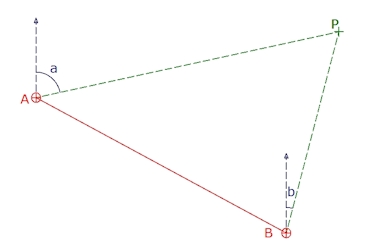 |
Given the E and N of A and B and the bearings a and b the E and N of P can be computed as follows: ( NA x tan ( a ) ) – ( NB x tan ( b ) ) – EA + EB NP = ————————————————————————— tan ( a ) – tan ( b ) ( EA x cot ( a ) ) – ( EB x cot ( b ) ) – NA + NB |
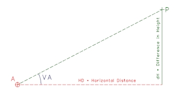 |
Once the E and N of a point have been calculated, the Horizontal Distance can be determined by Pythagoras: HD = Square Root ( dE2 + dN2 ) The difference in Height (dH) from the spherical panorama at A is the Horizontal Distance multiplied by the tan of the Vertical Angle (VA): Two values can be determined for the height of the point (P) from each of the spherical panoramas and compared to give an indication of the precision of the measurements. |
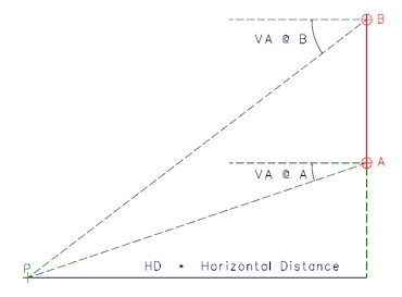 |
For two spherical panoramas with one vertically above the other, the Horizontal Distance (HD) to the point is calculated using the vertical Base distance between the two panoramas (BD) and the Vertical Angles to the point from the panoramas at A and B: |
![]()
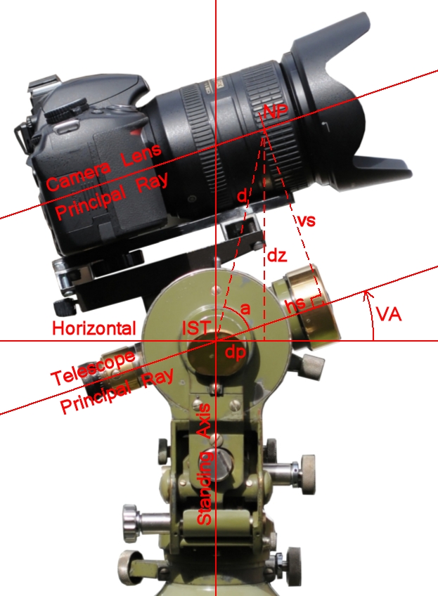
When using the projections from Spherical Panoramas the directions in space are from a single origin making the mathematics much more straight forward than when using a camera mounted on a theodolite as for Photographic Intersection. Not only do we need to consider the offset of the entrance pupil as shown below, but for most lens, especially fisheye lenses, the entrance pupil is itself a variable changing with the angle the rays enter the lens.
The relationship between the camera and the theodolite on which it is mounted can be considered as the difference in location of the entrance pupil of the lens and the intersection of the theodolite trunion axis with that of the telescope. The computation of the co-ordinates for the entrance pupil of the lens is from the location and orientation of the theodolite together with the three components representing the linear, lateral and offset of the entrance pupil.
The displacement of the Entrance Pupil of the camera lens and the intersection of the Standing and Trunion axes of the theodolite is corrected for using basic trigonometry.
If the co-ordinates of the intersection of the Standing and Trunion axes are X Y Z, then the co-ordinates of the Nodal Point (x y z) are calculated as follows:
tan a = vs / hs
d = square root ( vs2 + hs2 )
z = Z + dz = Z + d ( sin ( VA + a )
dp = d ( cos ( VA + a ) )
vs = Vertical Separation between the two Principal Rays
hs = Horizontal Separation between the NP and IST
NP = Null Point (Entrance Pupil) of the camera lens
IST = Intersection of the Standing and Trunion Axes
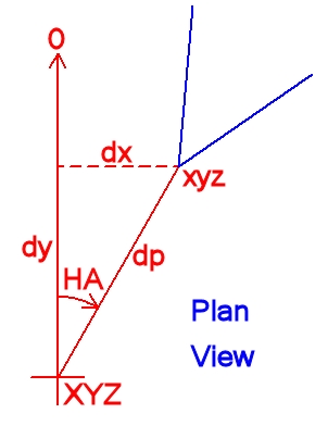
If the camera/lens axis is misaligned with the with the theodolite axis horizontally this can be corrected for as follows:
x = X + dx = X + dp ( sin HA )
y = Y + dy = Y + dp ( cos HA )
![]()