Author: Hugh Anderson 1st August 1978
Abstract
The paper describes the development of an optical device for use in detail surveying, which enables panoramic photographs to be taken using conventional cameras and lens systems, and suggests how such a device can be used as a tool in some survey disciplines.
Introduction
Large scale detail surveys require the fixing of points to which subsequent measurements can be tied to in order to enable the detail to be plotted. These points are usually fixed to a control network by one of two methods; line and offset, or radials. Both methods require the drawing of a field diagram to show the relationship of the points, and to which point is referred. The latter is the more commonly used method today, and involves angular measurements at the Control Stations and distance measurements to the points. The production of a diagram, or diagrams, for points fixed from the Control Stations is often a time consuming operation as it is necessary for the diagrams to be clear. Rough sketches often prove more confusing at the plotting stage than helpful. In surveying building interiors, a diagram is usually required for each room resulting in many more diagrams for a given area than when working in the open, which consumes more time.
If diagrams could be produced photographically, considerable savings in time would result, reducing the cost of surveys, especially building interior surveys. The problem was to record the relevant points of detail without extraneous coverage. This could be done by setting up a camera and photographing a full 360° by successive exposures at different pointings. For example: a 35mm camera fitted with a 35mm lens would require 6 exposures 60° apart horizontally for each Control Station. A 28mm lens would reduce the number of exposures required to 5 spaced at 72° intervals, but more extraneous subject matter would be included (sky and foreground). This method would require considerable care to ensure each exposure overlapped sufficiently to achieve full coverage, and it is probable an experienced Surveyor would be able to draw a diagram as quickly. Saving in time would thus be small, if any, whilst increasing the cost of equipment and materials required. The number of exposures should therefore be reduced to one, or two at the most, to make the saving in time effective. To achieve this I considered the use of a fish eye lens which produces a circular image covering a field of view of 180°. If such a lens is fitted to a camera placed with the film plane horizontal, the resulting image would have the relevant detail round the periphery. The disadvantages are that the relevant information is restricted to a narrow band at the edge of the circular format, and that only detail above an horizontal plane through the camera will be recorded. The remainder of the photograph will be sky with the sun possibly included. The use of a fish eye lens has however two considerable advantages; an horizon of 360° is
recorded in a single exposure, and the angles (directions) from the centre of the photograph to points of detail in the image are preserved as the angles (directions) from the camera station to the points of detail on the ground. The preservation of angles is important, because not only can time be saved with respect to the production of diagrams, but if the necessity to observe angles to detail points were eliminated a further considerable saving in the Surveyors time would result. Two methods for plotting the detail points fixed radially are in common use; computing co-ordinates from the observed angles and distance and plotting these co-ordinates, and plotting the radials directly using a protractor and scale. Considering the latter, a photograph with preserved angular relationships can replace the protractor eliminating the need to record observed angles and plot them later, thus eliminating two sources of error. The problem of producing a photographic diagram now crystallised into producing an optical device that would enable a camera to record an horizon encompassing a full 360°, include detail above and below the horizon and still preserve the angular relationships to the detail without including large areas of extraneous subject matter.
The Panoramic Optic
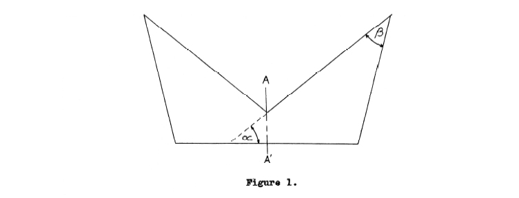
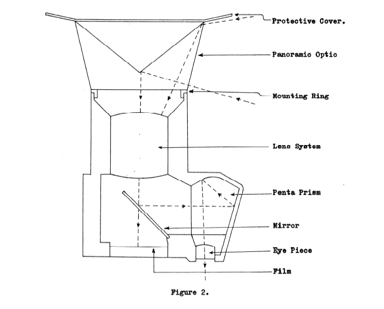
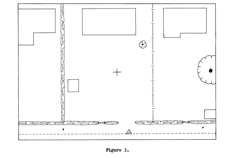
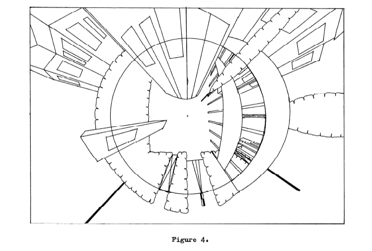
The requirements listed at the end of the last paragraph can be achieved by placing the panoramic optic in front of a conventional camera lens system. The optic is essentially a section through a prism, rotated through 360°. Figure 1 shows a section through the panoramic optic, the axis A A’ being the axis of rotation. Figure 2 shows a section through an optic mounted on a 35mm reflex camera with the limiting rays above and below the horizon (acceptance angles). This arrangement produces a specialised image. Figure 4 illustrates the image produced when the detail shown by the plan in figure 3 is photographed from the point marked by a cross. The circle in figure 4 represents the sensible horizon of the camera/optic combination and will not appear in a photograph. The specialised image in figure 4 s equivalent to a photograph made using a 35mm camera with a 35mm lens system and the angle oc = 38°.
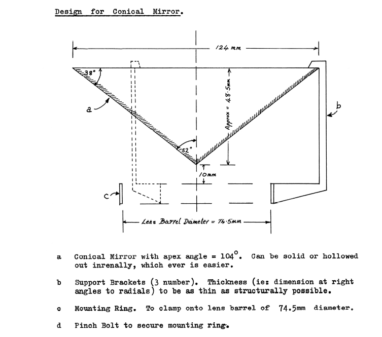
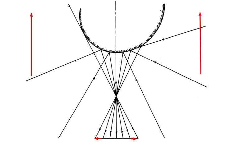
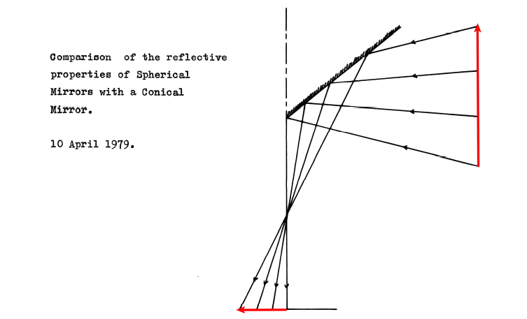
An inverted conical mirror occupying the same space as the totally reflecting surface would produce the same specialised image, but presents mounting problems as any supports would appear in the image. This could be overcome by supporting the mirror with a glass cylinder of suitable optical quality.
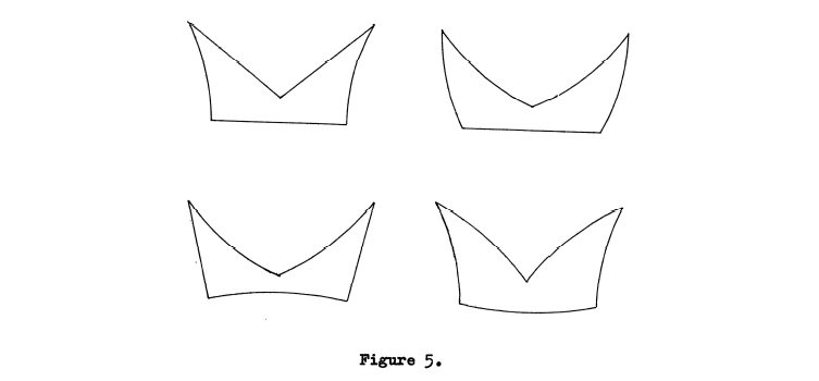
The acceptance angles of the optic are dependent on three factors; the film format, focal length of the lens system, and the angle oc in figure 1. The upper angle is dependent on all three factors, whilst the focal length has little influence on the lower angle. The acceptance angles can be altered by curving one, two, or all three of the surfaces of rotation as shown in figure 5. Curving one or more of these surfaces uses the refractive properties of the material used to construct the optic and could introduce colour aberrations unless care is taken in the design. With reference to figure 1, the refraction of the rays by the two surfaces through which the light passes will be the same if angles oc and B are made equal. With these angles equal the image produced by the optic will be the same as that produced by an inverted conical mirror with the apex angle of the cone = 180° – 2 oc.
Application
As mentioned in the Introduction, the development of the panoramic optic was for use in detail surveying where the preservation of the angles is of great advantage. This angular preservation can be utilised in other survey fields. The following examples illustrate three more possible uses for the optic. Other uses and development potential exist.
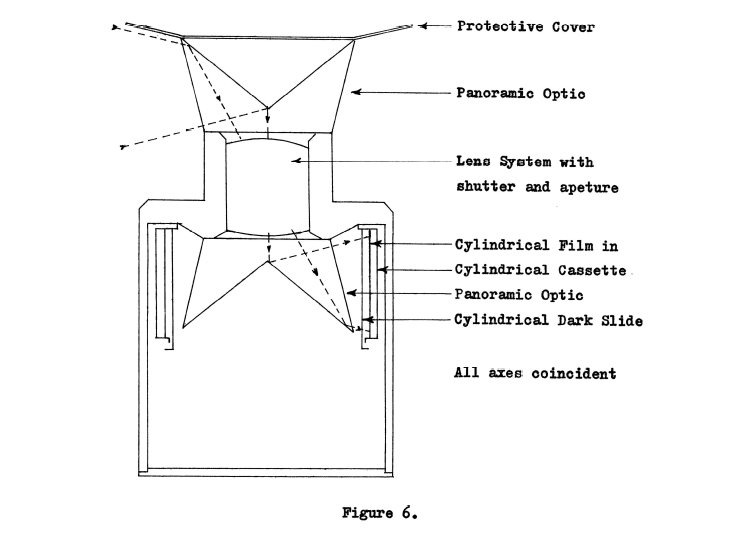
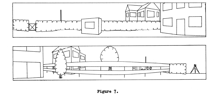
STATION REFERENCE DIAGRAMS: In the establishing of control (e.g. primary triangulation beacons) it is often necessary to produce panoramic diagrams from the station to enable subsequent users to identify the locations of other stations visible from the established stations. The same disadvantages to diagram drawing apply as in detail surveying; it is time consuming, and the resulting diagrams are often inaccurate or confusing. Two forms of photographic diagrams can be produced by employing the panoramic optic. The first, using one optic mounted in front of the camera lens as in figure 2 to produce the specialised image as in figure 4. However, it is possible to produce a coherent panoramic photograph covering an horizon of 360°. Figure 6 shows a camera using two optics to produce the coherent photograph with a single exposure, and without the use of either a moving lens system or moving film, during the period of exposure. The acceptance angles can be selected to exclude large areas of sky and foreground. Lenses of different focal lengths can be used to produce different acceptance angles for any single or pair of optics. The strip image (figure 7) produced by such a panoramic camera can also be produced by making the specialised image (figure 4) with the combination as in figure 2, which is then printed using a conventional enlarger, but with an optic mounted in front of the lens focused onto a cylindrical piece of printing paper whose axis of rotation is coincident with the axes of the lens system and optic. This system could also be used to record and project coherent panoramic images with slide or cine-film. The images being recorded as the specialised images, then projected through an optic onto a cylindrical screen, the axes again being coincident. The advantage of photographs over diagrams is that all visible objects from the point are recorded, and changes to the landscape are more readily discernible.
HYDROGRAPHIC SURVEY FIXES: Commonly used procedure to obtain a fix for a boat carrying out inshore hydrographic work is to use sextants to record the boats position. This is done by simultaneously reading two horizontal sextant angles to shore based markers of known position. The method requires two sextant observers, and errors can result from a number of sources; misidentification of one or more shore beacons, readings not exactly simultaneous, errors in observed angle recording, poor bisection of targets, sextant observations not taken at the same point, etc. I propose that all the mentioned error sources would be eliminated if the sextant observations were replaced by a single photograph for each fix made with a gimbal mounted camera fitted with an optic, their axes being vertical. To plot the fixes, the specialised images are projected vertically onto an horizontal surface (e.g. with a multiplex projector). The projected image can then be used in the same manner as station pointers. This does not allow for the observations to be computed. This however, can be done by using an electronic angle measuring device (as with coded elements) [1], or a protractor, built into the horizontal surface. The cost of an exposure per fix may initially appear expensive, but 15m of 8mm film can accommodate 4,000 exposures.
TRIANGULATION: The property of angle preservation with the optic allows for graphic triangulation using the specialised images formed. Mathematical triangulation is also possible if electronic angle measurements, or protractor angle measurements, are made from the images. The ease and precision of theodolite use on land however makes this application a non-starter in such an environment, but in unstable environments, such as on water, photographic angle measurement may well prove invaluable. There is another environment where mapping is still in its infancy, and photographic angle measurement may open up new survey methods to replace the cumbersome grid system now used. Underwater. Photographs taken of the sea bed and wrecks published in magazines such as National Geographic clearly illustrate the potential of photography as a mapping tool in this environment. I feel there is scope for photogrammetric techniques, especially with stereometric cameras, underwater. Photographic triangulation of pre-marks and or detail would considerably reduce the number of taped measurements required whilst greatly improving accuracy. A Nikonos fitted with a panoramic optic would be the diving surveyors equivalent of the land surveyors theodolite.
Conclusion
Survey techniques develop and evolve with the instrument changes brought about by technology, and many techniques fade in popularity only to reassert themselves later. For example, three hair theodolite tacheometry was largely replaced by self reducing tacheometers, which in turn, have been effected by advances in E.D.M. and Total Station instruments. However, with the introduction of programmable pocket calculators, three hair tacheometry is once more an economic and rapid means of fixing detail and spot heights. In attempting to speed up detail surveying by finding a means to produce rapid reliable diagrams, new survey techniques have been made possible using the panoramic optic devised. The optic is patented but research and development is needed.
References
[1] Gorham, B. J., 1976. Electronic Angle Measurement Using Coded Elements With Special Reference To The Zeiss Reg Elta 14. Survey Review, XXIII(180): 271-279.
Related material produced 1st March 1979

Related material produced 10th April 1979
![]()