
Practical Tests to Examine the Accuracy using 360° Panoramas for Measurement
The accuracy for a point measured using Intersection from two or more 360° Panoramas is determined by the following factors:
Angle of Intersection (Angle of Cut),
Separation of the Panoramas (Base Line),
Precision of the Angular Measurements (Resolution of the Panoramas) and
Distortion in the Panorama Images.
To evaluate these factors empirically I set up a test site in the summer of 2016.
Sixteen Targeted Points
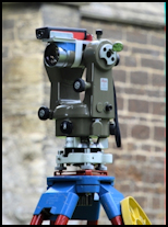 The first step was to co-ordinate Sixteen Targeted Points, which was done using a Kern DKM2-A 1″ Theodolite with a top mounted Leica DISTO.
Panoramas were then recorded at points co-ordinated in the same system using an FX DSLR and Samyang 8mm lens inclined at +7.5° taking four shots round as this is the configuration I use with this rig as it provides plenty of overlap for Control Point generation and using the “Mask” tool in PTGui where there is movement between shots and closes the zenith well.
The Panoramas were stitched using PTGui and the stitching was also investigated after the initial calculations, which were made using Excel.
The distribution of the Targeted Points are as shown on the Sixteen Targeted Points page.
The calculation were made from pairs of Panoramas.
The initial calculations were made using Horizontal Angles derived from the targeted centre of the second Panorama and Vertical Angles derived from the “equator” of the Equirectangular projection, which provided encouraging results for the x and y co-ordinates when compared with the values measured with the Theodolite, but the difference in z values were some four times greater than those for the x and y differences.
The data was recalculated using the targeted centre of the second Panorama as I remembered that when using Panoramas to colour the points in an HDS Point Cloud that the Panorama was “fitted” to the Point Cloud by a minimum of three points, each of which was on a different Cube Face as described in Spherical Panoramas for HDS Point Clouds (Page 25 and following) and iSTAR Panoramas for HDS Point Clouds (Page 18 and following).
This provided a much better agreement for the z values and suggested that tilting the camera up by +7.5° produced distortion in the Equirectangular image.
Angle of Intersection (Angle of Cut)
It is clear from the results that by far the biggest influence on accuracy is the angle at which the rays in space intersect.
Although the points were not best distributed to cover the range of Intersection Angles, the graph below shows that the closer to 90° the more reliable the result.
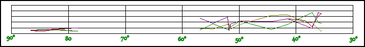
This result is consistent with the information on Accuracy for Intersection Solutions.
It is also worth noting that it is not the Intersection Angle as shown on a Plan that should be considered, but the angle in space.
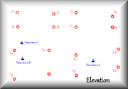
In the following plan, the black symbols show the Targeted points in their true plan positions and the red symbols how they are displaced when plotted using the slope distances showing how the Intersection Angle is reduced as the Vertical Angles to the points increases or decreases from the horizontal.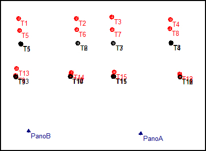 Separation of the Panoramas
Three “base lines” were used in the calculations; A to B with a horizontal separation of 4.618 metres, A to C with a horizontal separation of 4.666 metres and vertical separation of 1.141 metres and B to C with a vertical separation of 1.000 metre.
The vertical base line between B and C produced very poor results because the angles of cut (Intersection Angles) were acute due to the distance the points were away from the Panorama locations, which again is consistent with with the information on Accuracy for Intersection Solutions.
The length of the base line has a direct bearing on the Intersection Angle so that it should be selected to try and get these as close to 90° as possible.
This suggests that using a vertical base line is really only suitable for measuring points close to the Panoramas.
Resolution of the Panoramas or Precision of the Angular Measurements
The resolution of the Equirectangular projections used to measure the Horizontal and Vertical Angles should have an influence on the accuracy achievable so the panoramas were stitched in PTGui then output at three different resolutions to see what effect the differenced in resolution would have.
The table below shows the distance subtended by one pixel in the relevant Equirectangular at 5 metres, 10 metres and 20 metres.
| Resolution | Angle in ° | Distance @ | |||||||
| Pixels | MP | per Pixel Width | 5 m | 10 m | 20 m | Equivalent to | |||
| 12000 | x 6000 | 72.0 | 0.0300 | 0.003 | 0.005 | 0.010 | FX DSLR + 8mm | ||
| 7776 | x 3888 | 30.2 | 0.0463 | 0.004 | 0.008 | 0.016 | Samsung Gear 360 | ||
| 5376 | x 2688 | 14.5 | 0.0670 | 0.006 | 0.012 | 0.023 | Ricoh Theta S | ||
It can be seen that the distance subtended by one pixel in the relevant Equirectangular is only a few millimetres, especially at a range of 5 metres or less, and that most of the values from comparing the two lower resolution Equirectangulars with the 72MP DSLR solution are in the ±3 mm range. 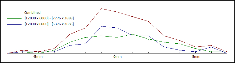
Distortion in the Panorama Images
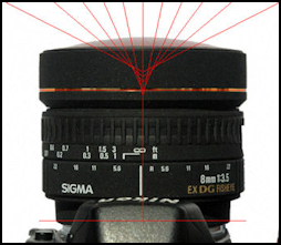 Stitching the images together will align them relative to each other, but matching Control Points will also “correct” for distortion in the camera lens. A fisheye lens has huge amounts of radial (barrel) distortion which is evident by the way the NPP (No Parallax Point) slides towards the front of the lens as the angle of incidence increases.
 A camera lens is constructed from a number of elements, each of which is a lens in its own right, and although each of these lenses may be near perfect they may not be perfectly aligned in the final assembly. These elements move each time the lens is focused and returning the lens to the same point of focus having changed the focus will not necessarily replace them in exactly the same position. In the early 1980’s we calibrated off-the-shelf camera lenses for use in close range (Terrestrial) Photogrammetry and this was immediately obvious so the lens was “locked” before calibration with either a grub screw or electrical tape.
A zoom lens will also change the relative positions of the elements each time the zoom is changed.
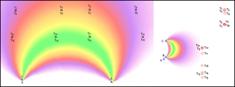
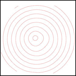
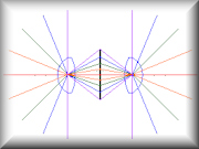
A contour map for radial distortion for a fisheye lens with perfectly aligned elements would have concentric circles, but the reality is more likely to be as shown in the diagram to the left.
Stitching will result in distortion in the final panorama, which will in turn result in inaccuracies in measurement which will vary depending on the location of the measured point.
![]()
 |
Sixteen Targeted Points |
|
 |
Single Lens v Multi-lens Cameras for Measurement Accuracy |
|
 |
Spherical-Panoramas-for-HDS-Point-Clouds |
|
 |
iSTAR-Panoramas-for-HDS-Point-Clouds |