My first encounter with stereo images and photogrammetry was as a school lever in 1965. I was working for J. A. Story and Partners in Kenya when we visited the remote West Pokot region in western Kenya. Mapping was required for a potential platinum discovery and I was impressed by the fact that such a large area of Africa could be mapped with only a few days in the field even with the difficult logistics presented by the area. The transportation of the theodolites, Tellurometers and batteries had to be by porters because of the nature of the terrain, but the agricultural people at the tops of the 1000m high hills did not readily mix with pastoral people in the valleys so we had to change porters half way up and again on the way down! I was also very impressed by the 3D images when viewing the stereo aerial photographs through the stereoscope. Little did I know then how much of my life was to involve photogrammetry in many parts of the world.
 In 1973 I encountered Terrestrial or Close Range Photogrammetry when I was privileged to field test the Wild P32 camera that had just been introduced into the UK. The first project this was used for was to map the façade of a bridge in Lancashire for a road-widening scheme. Terrestrial Photogrammetry lent itself as the solution to this task because the landowner on the north side of the river exercised his riparian rights and forbade the crossing of the river centre-line onto his property. However the next task that the Wild P32 was used for was of much greater interest.
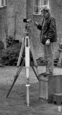
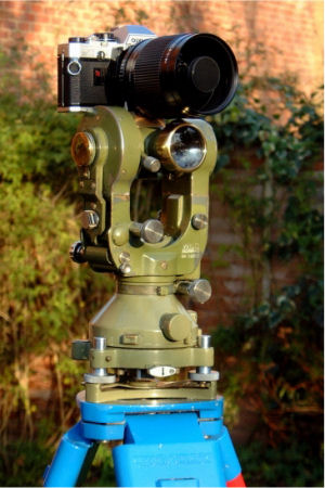
A baronial mansion, Annesley Hall north of Nottingham, with a cellar dating back to Norman times, was to be mapped in its entirety. The Wild P32 was to be used to map all the external facades of the main building and the stables by Terrestrial Photogrammetry. The fact that the Wild P32 was mounted on the top of a Wild T2 theodolite meant that the position and orientation of each and every photograph could be recorded and that the camera could also be accurately positioned at specific locations for taking the photographs. I carefully marked out the camera locations and took considerable effort to ensure that the camera was at the correct 3D location for each photograph as is evident from the photograph. I also placed Photo Control Points on the surfaces being mapped because it was not standard practice to know the location and orientation of the camera at the time of photography. These were positioned in the ideal locations for the photography because I knew exactly the area covered by each photograph. In the event, the Photogrammetric Operators ignored the information about the location and orientation of the photographs and used the Control Points as in conventional aerial photography turned on its side. However, the information relating to the camera location and orientation meant that the facades could have been mapped from the photographs by Photographic Intersection without using a Photogrammetric solution. With today’s technology, computers and digital images, this could be a more expedient and accurate method, but these things were still in the future at that time.
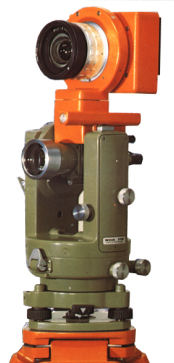
The concept of Photographic Intersection predates the invention of photography itself. Surveyors produced drawings in the field by projecting an image onto a surface using a lens, then tracing in that image. Maps were then produced from these images in much the same way as we use photographs for Terrestrial Photogrammetry today. This process was given a considerable boost by the invention of the 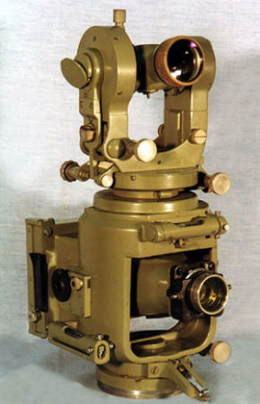 P30 Photo Theodolite by Heinrich Wild of Heerbrugg in around 1922, half a century before the Wild P32 camera arrived in the UK. The theodolite portion of the Wild P30 incorporated the elements of the legendary
 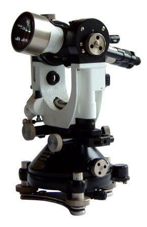 Wild T2, also invented by Heinrich Wild in the early 1920s, which was a major innovation in the world of surveying instruments.
In May 2001 I was invited to present a paper at the Word of Surveying conference held at Donington Park. We were requested not to use the opportunity to simply promote our products, but to provide presentation that would be interesting to the audience. The experience of the previous year showed that the sales pitch approach of some of the presenters caused the audiences eyes to glaze over and heads to nod, so I closed by suggesting that data could be delivered in a form different to the conventional line drawing. The information contained in a photograph is much much more than that shown by a line drawing. Show an Orthophoto, or even a conventional aerial photograph, to people and they instantly recognise features such their own homes. Show them a conventional line map and you might just as well have presented them with a text in Latin! We live in the age of digital images so I demonstrated how most imaging software, such as Photoshop or Paint Shop Pro, have attributes behind the image. Click on a pixel and you are presented with information about the colour make up and co-ordinates of that pixel. Providing that the digital image is never manipulated, these values will never change. No matter how many times the image is copied, transmitted or viewed, the attributes of the pixel remain the same. My suggestion to my audience was that we could add information such as the origin in space and orientation of that pixel from the origin.
Orthophotos of relatively flat terrain from aerial photographs are easily produced with today’s technology, but Orthophotos from Terrestrial or Close Range Photogrammetry present a challenge. Rectifying planes is straight forward, but much of the detail on say building facades is too variable to be correctly rectified, which means scaling off such an image cannot be relied on. However, imagine being able to view digital images that are not rectified photographs or Orthophotos, but when an object in the image is clicked a ray in space with a known origin and orientation is calculated and clicking on the same feature in another image calculates another ray in space with a known origin and orientation. The result is a 3D co-ordinate (x, y and z). Click on the same feature in three or more images and we have 3D co-ordinates with an indication of the precision and quality of the result.
I started developing my Photographic Intersection ideas whilst carrying out the survey of Annesley Hall. The main building contained a myriad of rooms. There were four floors with mezzanine floors between and the roof space and roofscape to map. The nature of the building meant that the rooms were not rectangular and there were many hidden spaces including priest holes and a completely sealed off room above the main entrance. To tie the rooms together I used a technique which was considered controversial at the time. I traversed through the building using a Wild T2 and Wild DI10, but most of the measurements were made by tape and using tools that I had to specially develop for the task. I thought long and hard as to how I could make the task less labour intensive and laborious. There must be solution involving photography!
 I first came up with the idea of using a camera fitted with a fish-eye lens. By placing the camera on its back at a known location, the resulting image would have the points of interest radial from that point. Unfortunately, the nature of a fish-eye lens meant that the part of the image that was of interest was in a narrow band around the circular edge of the image, and were therefore difficult to distinguish. However, the principle was there and this lead to my invention of the conical mirror or conical prism. This provided a distorted image, but one in which all the points of detail were radial from the centre of the image. By taking two or three such images in a room at known co-ordinates these images could be used to plot the room by Photographic Intersection. Using a photographic solution meant that all the detail on the room was capture at one time so that if additional detail needed to be plotted, this could be done without having to revisit the site. I was granted a Patent for this invention in 1975, but being of very limited funds I let this lapse when the laws were changed in the early 1980s and the annual fees increased dramatically. Within a year or two of letting the Patent lapse I noticed that Kodak Carousel Projectors were using conical prisms so that the infra red signal to change the slides could be detected from any part of the room. Conical mirrors are used to today in laser levelling devices and perhaps most galling of all is that Trimble (Geodimeter) uses a conical mirror for their 360° active detector for their “robotic” Total Stations. The digital computer was still in the future and would have been a great asset in developing this technique, but actually presents more suitable solutions.
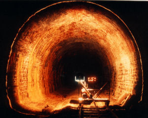 A method of Photographic Intersection did solve a real problem at the beginning of the 1980s. Due to a tunnel collapse in Glasgow with fatalities, it became desirable to know if there were any distortions in Railway Tunnels. Stereo Photogrammetry was considered a solution but it was soon discovered that there was a huge difference between measuring images that the principal rays of the cameras were perpendicular to, as in aerial photogrammetry, and measuring images where the subject was parallel to the principal rays, such as in a Railway Tunnel. This was not helped by the fact that the tunnel walls were also black from years of soot and grime. Ian Waite had used a flash gun sandwiched between two sheets of plywood to illuminate sections to determine overburden when tunnelling for the Dinorwick Pumped Storage Scheme in Wales. It was considered that if such a “light line” could be introduced into the stereo images then the photogrammetric solution would be viable. Two Companies addressed this problem, Photarc Surveys in Harrogate, Yorkshire and BKS Surveys in Coleraine, Northern Ireland. The BKS team consisted of David Stevens and me.
The solution to produce a very narrow but bright light line came to me in the wee hours one morning and my wife was not too pleased about being woken up for me to ask where the flan tins were kept, but FITS (Flash Illuminated Tunnel Section) was born. Even with the light line, Stereo Photogrammetry was too slow in the field and time consuming back at the Photogrammetric Workstations. In order to attempt to speed up the data acquisition in the field, we mounted the cameras, two Wild P32s, on a beam on a rail trolley connected by a rigid bar to another trolley with the FITS unit on. Using such an arrangement meant that the camera to object distance was always a constant so why not use a single photograph with the known geometry? This proved to be a very effective solution and we could capture data for one Kilometre of tunnel, with a section every 10 metres, in a single night. This is a method of Photographic Intersection as the intersection of the ray from the camera with the plane of the light line are the points of interest. This solution was enhanced by introducing car headlamp bulbs into the unit so that the light line was on continuously, which meant that the distortions in the tunnel could be observed as HITS (Halogen Illuminated Tunnel Section) as we now called it, was moved along the tunnel. This method was successfully used to map both railway and canal tunnels. Patents were applied for and a United States Patent was granted with the proviso of the completion of a United Kingdom or European Patent. Had we gone for a United Kingdom Patent we would probably have been successful, but the costs of trying for a European Patent seemed to be spiralling out of control so we eventually abandoned the application. Today a special locomotive with a built in light line generator is used to survey railway tunnels.
Using photography as a means of data capture is a rapid way of gathering large amounts of information. Direct measurement methods are time consuming on site and, although it may sound obvious, only those points measured are captured. A photograph may be taken to capture a limited amount of data at the time, but a huge amount of additional information is captured at the same time for no extra effort. This information can be extracted later without the need to revisit the site, bearing in mind that the site could have changed, or may even have ceased to exist.
Photogrammetric cameras tend to use wide-angle lenses to capture a large amount of information and ensure good intersection of the rays to the points of interest. However, if we replace the Wild P32 on the Wild T2 with say a 35mm camera with a 1000mm lens we have a different, but very useful device. This focal length covers a zone approximately 2° on the long side and 1° 20’ on the short side, or some 7200 x 4800 seconds of arc. If the resultant image could be digitised to a matching pixel resolution, which is possible with equipment available today, then each pixel would represent one second of arc in the image. Digitisers with half this resolution, say 3600 x 2400, are reasonably priced and would still provide the equivalent of a two seconds of arc resolution. The relationship between the lens and the theodolite is readily calibrated. Calculations of the co-ordinates from such images would provide a method of rapid data capture in the field with a high order of accuracy. Data can be easily extracted from these images away from site and in comfort using software that would take little to develop as all the components are in use today.
Photogrammetric cameras, such as the Wild P32, are designed and manufactured so that lens distortion is virtually non-existent unlike the lenses used for regular photography, but even this is taken care of with today’s digital imaging technology. Software packages, such as DxO and PTLens remove the lens distortion for digital cameras and zoom lenses using the exif information included in the digital image.
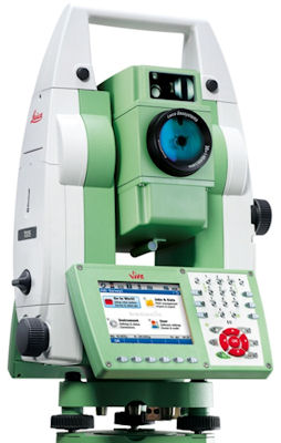 Theodolite Intersection still provides the most accurate method of measuring objects remotely. We can expect sub-millimetre accuracy over ranges in excess of 100 metres when using top-of-the-range Instruments such as a Leica Viva Total Station or TS30. The technique also provides a feel for the quality of the observations. However, the data capture process in the field is time consuming as each point must be observed from a minimum of two, and preferably three, Instrument Stations. Mistakes can easily be made in identifying the same point of interest from the different Stations. The information you take away from the field is only the discrete measured points. Additional data will require another site visit, but the site could have changed, or may even have ceased to exist.
Reflectorless Measurement also requires less time in the field than Theodolite Intersection as each point needs only to be measured from a single Station, but is still considerably more time consuming than Photogrammetry. Accuracy is better than with Photogrammetry but not as good as with Theodolite Intersection and is more dependent on the accuracy of the Reflectorless EDM than angular accuracy of the Instrument. The accuracy of the Reflectorless EDM is affected by the nature of the surface being measured to, and there is no information as to the quality of the individual measurements. Once again, the information you take away from the field is only the discrete measured points. The range is restricted by the Reflectorless EDM.
However, Image Assisted Surveying creates new possibilities for both Theodolite Intersection and Reflectorless Measurement surveys and offers new opportunities for Photographic Intersection.
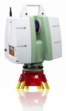
 Scanning with a system such as Leica Geosystems HDS creates a large “point cloud” in a very short space of time, so the field time for data acquisition is very short when compared with Theodolite Intersection and Reflectorless Measurement. The density of the ”point cloud” is determined at the time of measurement so missed discrete points or areas would require revisiting the site, although the “real time” display of the data should enable the user to ensure that everything of interest is covered at the time of survey. The equipment is however still relatively large, heavy and expensive when compared with the other techniques, but is the future as far as collecting 3D data to the precision required by Surveyors and Engineers.
Terrestrial Photogrammetry requires much less field time than Theodolite Intersection, but accuracy suffers as the camera locations are reconstructed from Photo Control Points in the images, and these points have to be measured using another technique, such as Theodolite Intersection or Reflectorless Measurement. A considerable benefit is that a huge amount of information is captured in the images and this can be extracted at any time in the future. If the subject only appears in a single photograph it can often still be measured using the geometry of the structure and the single image.
Photographic Intersection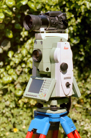
 involves little time in the field to capture a large amount of data that can then be extracted as and when required. Accuracy will not be quite as high as for Theodolite Intersection, but will probably be better than with Reflectorless Measurement, depending on the pixel resolution. Accuracy will certainly be better than with Stereo Photogrammetry and probably better than with a Scanning system. This could be the most cost-effective solution for a huge number of subjects. I am promoting Photographic Intersection as a low cost solution for capturing 3D data to a high order of accuracy because the equipment required is easily obtained at little cost and the mathematics involved is straight forward trigonometry.
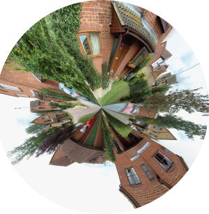
Photographic Intersection – A Special Case: The power of the ubiquitous digital computer and digital photography coupled with ingenious software such as PTGui and Pano2VR enable the creation of Spherical (360°) Panoramas, which have the property of a Gnomic Projection in that the the points in the image can be considered as directions from the centre of a sphere. If the location of the point of rotation of the images (the Nodal Point of the lens) is known, these directions can be used to compute 3D points from two or more Spherical Panoramas. Spherical Panoramas can be utilised in a number of arrangements such as Equirectangular or Cube images and even projections familiar to the Surveys such as Mercator. The geometry of these transformations (outputs) mean that points in such images can readily be converted into directions (Horizontal and Vertical Angles) from the centre of rotation (origin) for a particular Spherical Panorama. Directions from suitably arranged Spherical Panoramas can then be used to compute the 3D co-ordinates for points selected from the images.
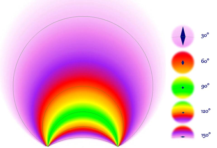
It is imperative that cognisance is given to the accuracy of points computed by intersecting rays as maximum accuracy will only be achieved where the directions intersect at right angles and will fall away as the angle changes.
The following image demonstrates the accuracy from using this method from two Spherical Panoramas. The actual values will depend on a variety of factors including the accuracy to which the Panoramas are created (resolution), their separation (base line) and the precision of the picking of the points in the images.
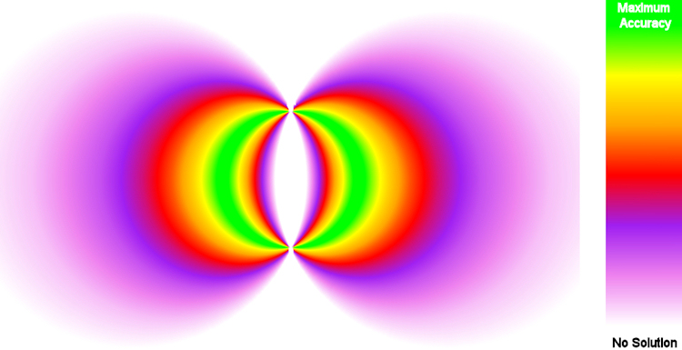
The following image shows the relative size and shape for the theoretical precision as the angles of intersection move away from the optimal 90°.
![]()