
Having experimented with a variety of methods to determine the NPP (No Parallax Point) including those in “Finding the Nodal Point of a Lens” for nearly half a century I have found the ‘Pins & Tape Measure’ method in various forms provides an accurate results and, in the digital age, is convenient, especially for cameras with fixed lenses.
This method uses the location of the ‘pins’ registered with the point on the ‘tape measure’ they cover to construct the rays back to the lens position. The requirements are the ‘pins’ and target ‘tape measure’ and a surface into which the pins can be pushed or tapped into and which can be drawn on, such as sheet of 8’ x 6’ x ¼” plywood (2.6 m x 1.96 m x 6 mm).
In March 2021 I wanted to determine the NPP for a Pergear 7.5 mm Fisheye and, whilst I had the board set up, to see what results I would get with a couple of dual lens single shot cameras. I had a sheet of 900 mm x 600 mm x 6 mm plywood which I considered suitable and taped printer paper to it with masking tape so I did not have to draw directly onto the wood as it would probably have a different use in the future.
The first task was to drill a ¼” hole near the edge to of the board (M) so the camera can be secured so it could not be knocked, or perhaps more importantly, so it could not be knocked to the floor. I then drew a line up the board through the centre of the hole to represent the principal ray of the lens. Two lines were then drawn perpendicular to this line, one for positioning the pins and one for positioning the tape measure.
There are two methods of determining the NPP: graphically by drawing a line defined by the pin and the point it covers on the tape measure back to the lens position, or using a CAD application. The advantage of using a CAD application is that you can ‘zoom’ in to see exactly what is happening at the NPP location and you can include points that fall outside the board, such as the rays at 45° and 60° to the principal ray in this example.
To determine the NPP graphically the rays can now simply be drawn as described in the previous paragraph, but if a CAD application is being used it is necessary to measure the locations of the pins and the tape measure.
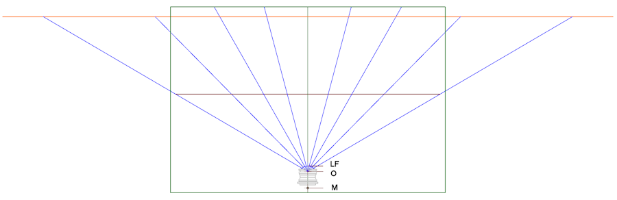
I used a CAD application and to keep it ‘neat’ I created an origin point (O) at where I guessed the NPP would be and drew the line for the pins 250 mm from this point and the line for the tape measure 500 mm from this point then lines, also from this point, at 15° intervals from the principal ray and placed the pins where these lines intersected the line for the pins.
The tape measure was fixed by securing it to a length of wood (approximately 2000 mm x 25 mm x 25 mm) with ‘electrical tape’ then clamping this to the board so that the face of the tape was along the appropriate line. I placed the 1000 mm point of the tape measure where it intersected to principal ray, but this is not necessary, especially if plotting the rays graphically.
The location of the lens including the front of the lens (LF) can be orthographically projected onto the paper using a set square.
Once everything is set up a single image is captured and viewed on the computer where it is possible to ‘zoom in’ and see exactly where the pin intersects the tape measure. The points for the pins and where they intersect the tape measure are then entered into the CAD application and the rays constructed from the point on the tape through the pin location. If the lens principal ray is perfectly aligned with the drawn line then the constructed rays should meet on the principal ray, but if it is not quite coincident then the NPPs will be on one side or the other which is why it is preferable to set up the pins symmetrically.
The position of the lens and the NPPs can now be applied.
January 2021
![]()