
Determination of the No Parallax Point (NPP) of a Lens Using a Laser Pointer
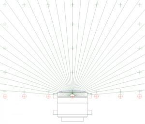
When the laser beam travels along the path of a ray that meets the No Parallax Point (NPP) of a lens system, a very bright spot is seen on a surface (white card) placed behind the lens and the ray can then be drawn onto the paper. These rays can be constructed for a variety of angles of incidence and the NPP determined.
Using a laser is an ideal method of determining the NPP of a lens and only requires the lens itself, unlike the Pins & Tape Measure method.
Working Surface
A table or board that paper can be taped to and that is large enough to accommodate the lens and laser alidade should be used, but should not be too large which would make working around the lens difficult.
Lens Cradle
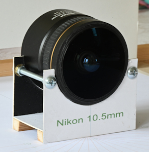
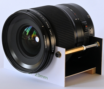 The lens needs to be supported so that the axis (principal ray) is parallel to the working surface and at the same height as the laser.
If the lens is heavy it may stay secure in its location on the surface due to its own weight, but it may be necessary to fix the lens cradle to the surface to avoid any movement during the mapping process, especially with a light lens and while recording the position of the lens.
I have constructed my lens cradles from stiff board, which I cut with a scalpel and glued to wood runners, but a variety of materials can be used including perhaps plasticine, Sugru or even 3D printing.
 If the lens being measured fits a film camera body and you have one to hand then this could be a suitable method for supporting the lens as described in “Using a Laser Pointer …”
Mapping the Lens
The lens should be carefully mapped using precision measurements with tools such as Digital Vernier Calipers or Electronic Calipers rather than rely on the measurements to locate its position on the paper with setsquare and probe.
Laser Alidade
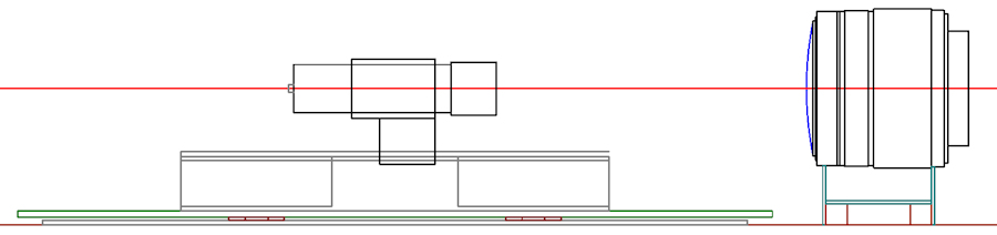
The laser should be mounted rigidly and vertically above the ‘ruler’ used to draw in the rays and must be the same height as the axis of the lens being measured.
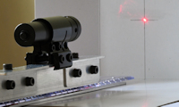
 Laser pointers are readily available, but the laser beam is often not accurately aligned with the barrel and usually the switch has to be held to keep the laser on. The later can be solved with tape, but the misalignment of the laser is more challenging. Laser gun sights are readily available at not much more cost and have the advantage of a regular on off switch and the laser can be adjusted to align with the barrel making it more suitable for determining the NPP. Laser gun sights also usually have a clamp to fit 11 mm and 20 mm rails so can be rigidly fixed to the alidade.
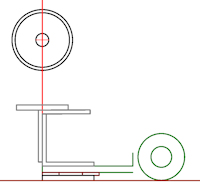 Using a Parallel Lines Glider Ruler as a base for the alidade makes it straight forward to align the ‘ruler’ along a line on the Template and move the laser parallel to the line.
The Parallel Lines Glider Ruler I used had a ‘slope’ of some 3° from the roller to the drawing edge because the wheel protrudes. This makes it difficult to arrange for the laser beam exactly above the drawing edge so I built up the drawing edge with an aluminium bar and washers so that the ‘deck’ was now ‘level’.
Laser safety: When using lasers ensure that they are used in a safe manner and always follow the manufacturer’s safety instructions.
Aligning the Laser
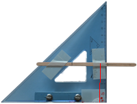
 To be able to align the laser correctly a line was drawn on some card which was then bent along a line at right angles to this then a cross marked at the height of the laser and axis of the lens.
Template
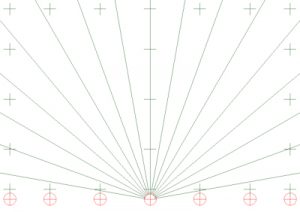 The laser can be used to record random rays and measure where they intersect the principal ray to determine the NPP, but it is more effective, precise and efficient to plot the rays at regular intervals such as every 10° or even 5° using a Parallel Ruler.
The template should also include Control Points so that it can be orientated and scaled correctly when scanned to determine the NPP digitally using a CAD application.
Positioning the Lens
The proceeds is more effective, precise and efficient if the lens is positioned as close to the correct location as possible so it is worth using the laser to align the axis of the lens and then move the lens along this line with the laser at 45° each side of the axis. This can be a ‘fiddly’ operation, but will make life easier later on.
Lens Location
 It is imperative that the position of the lens is recorded relative to the lines plotted using the laser. The position of the lens can be mapped using a ‘probe’ which can be constructed using a set square. This should be used to position the ‘mapped lens’ rather than to ‘map’ the lens as there are likely to be small (sub millimetre) errors in this process. Make a note of the points plotted using this process.
Recording the Direction of the Rays
 Line up the ‘ruler’ edge of the alidade with a line on the Template then move the alidade parallel to this line until a bright spot is observed on the surface (white card) behind the lens. As the alidade is moved back and forth the laser spot will appear to wax and wane much like the phases of the moon. When the laser spot is at its brightest (as for a full moon) the direction should be plotted.
This process is repeated for each angle line on the Template.
The number of rays that can be recorded will depend on the angle of view of the lens.
Care must be taken when moving the laser alidade back and forth as it is possible to introduce a slight skew which will introduce error into the measurement. Such an error will manifest itself more for the rays with a narrow angle to the principal ray (e.g. 10°) than rays cutting the principal ray at a greater angle (e.g. 60°).
It is the rays intersecting the principal ray at the larger angles that we are interested in for applications such as 360° Panoramas and stitching images in PTGui but care should be taken at all the angles.
Graphical Interpolation
Once the positions of the lens and the rays passing through the NPP have been plotted the NNP can be interpolated by projecting the lines plotted at the various angles to where they intersect the principal ray (lens axis).
This solution is sufficient for some application but a more rigorous solution can be achieved by scanning the plots and using a CAD application to determine the NPP.
Digital Interpolation
Interpolating the position of the NPP using a CAD application will provide a more precise solution than the graphic interpolation.
In this example the plots were scanned at 600 dpi.
There are a variety of CAD applications suitable for digitally interpolating the NPP.
In this example I have used LISCAD, a Survey and Engineering application, which incorporates a Background Images module allowing the scanned images of the plots to be orientated and scaled using the Control Points on the Template.
Being able to view the data at a scale larger than 1:1 (as in the graphical case) on a computer increases the precision of the result.
Second Iteration
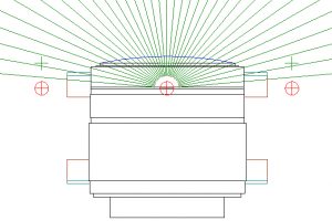 The precision of the determination of the NPP can now be honed by using the results to add the lens detail to the Template and repeating the measurement process as doing so will mean much less movement of the alidade away from the lines drawn on the Template, so less risk of introducing any skew and resulting errors.
Some lenses have more movement of the NPP along the principal ray than others. For example the Nikon 10.5mm Fisheye has some 6mm difference between the NPP at 10° either side of the principal ray and at 70° either side of the principal ray .
In such cases the measurement can be further enhanced by creating a new Template with the rays passing through the relevant NPPs instead of a single point as there should be little or no deviation from the drawn lines to get the maximum laser spot for each line.
March 2023
![]()
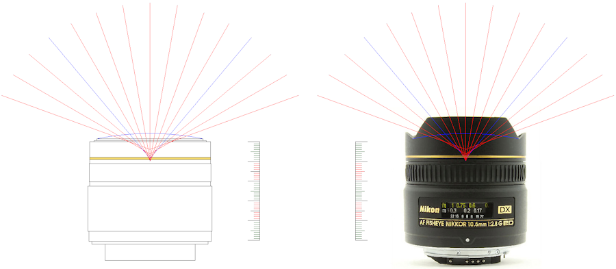
‘Shaved’ Nikkor 10.5mm Fisheye Lens – A DX lens usable with an FX format with the integral lens hood removed
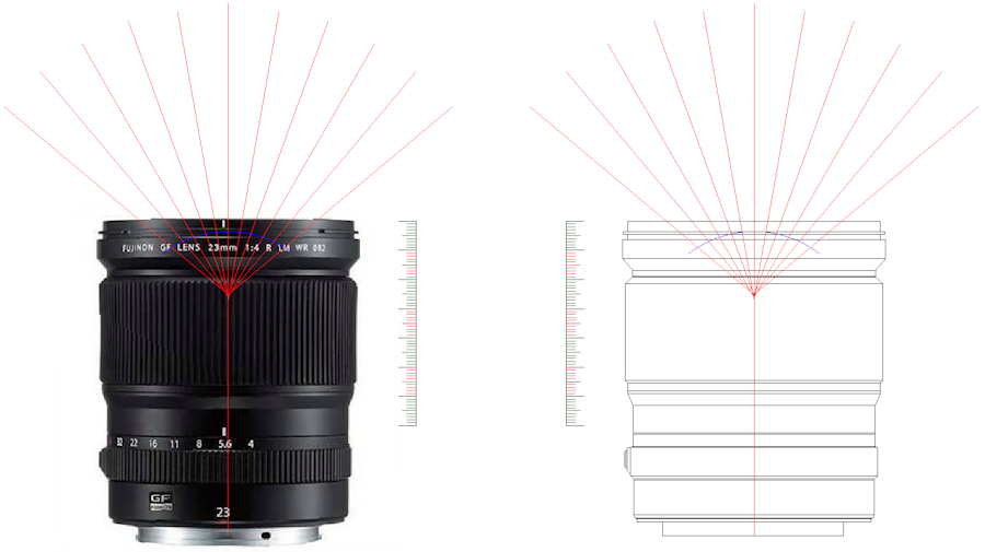
Fujinon GF Lens 23mm 1:4 R LM WR