Using Thermal Images to create a 360° (Interactive) Panoramas
Introduction
This report is the result of an investigation into the possibility of using images from a Thermal Imaging Camera to create a 360° (Interactive) Panorama to generate the Cube Images to attach the colours from the thermal images to an HDS (High Definition Survey) Point Cloud.
The Thermal Imaging Camera used for this investigation was a testo 875, for which the thermal image has a resolution of 160 x 120 pixels.
The investigation showed that it was possible to produce a 360° Panorama from the thermal images. However, the results were not of high quality because of the low resolution images. The investigation also showed that a disciplined approach is required to achieve a solution. The process is also much more time consuming, manual and labour intensive than creating 360° Panoramas with a DSLR and Fisheye lens.
Data Collection ~ Recording the Images
Preparation
To create a 360° Panorama the thermal images need to be taken with the Nodal Point (Point of Least Parallax) coincident with the point of rotation of a panoramic head, which in turn needs to be coincident with the central point of the HDS scan.
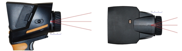
The first task therefore was to determine the Nodal Point, Entrance Pupil, for the Testo 875 and this was found to be 30 mm back from the front of the camera lens.
The Panoramic Head I have available for testing is a Nodal Ninja 3, which is designed to record images with a camera (DSLR) in portrait mode.
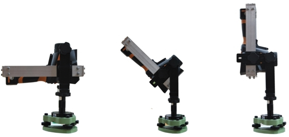
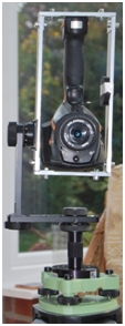 The testo 875 is fitted with a 6 mm thread in the base of the battery compartment handle and provided with an adaptor to convert this to a 1/4” Whitworth thread for fitting to a tripod, so the next step was to manufacture a frame that would enable the testo 875 to be fitted to the Nodal Ninja so that it could be rotated about the Nodal Point.
The frame was constructed so that the testo 875 could be mounted in both Landscape and Portrait format. The 6 mm thread was used to fix the camera into the frame as this was a more positive fitting than using the adapter. In hind sight it was clear that the frame was considerably over engineered, as a result of being able to obtain suitable materials in the time available, and weighed in at 650g. The testo 875 weighs 900g giving a combined weight of 1550g, which is around the limit that the Nodal Ninja 3 can handle. With the testo 875 in Landscape orientation the centre of gravity is close to the axis of rotation of the Nodal Ninja, but in Portrait orientation the centre of gravity is along way from this putting a lot of strain on the panoramic head, so the tests were made with the testo 875 in Landscape orientation.
It is possible to construct a much lighter, but equally robust, frame if further testing is required.
Recording the Thermal Images
The thermal images recorded with the testo 875 have a Field of View of 32° x 24° with a resolution of 160 x 120 pixels, which is equivalent to a 55 mm lens on a 35 mm camera or a 36 mm lens on a DSLR with an APS-C sensor.
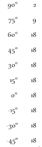 To obtain a good overlap between the images with the testo 875 in Landscape orientation the appropriate detent ring to use with the Nodal Ninja 3 was one with 18 pointings with 20° horizontal separation and to use 15° separation vertically. With the camera at 75° the horizontal separation can be relaxed to every other detent pointing and at 90° (vertical) reduced to two Images, giving a total of 155 images.
To provide a bench mark for the investigation a set of images was recorded with a DSLR and these images were made to have the same geometry (Field of View) as the testo 875. These images were recorded with the Nodal Point of the lens coincident with that of the thermal camera.
 The process was started with the camera horizontal (0°) and rotated clockwise. After the first 18 images were recorded the camera was elevated to 15° and the process repeated. This pattern was repeated increasing the elevation by 15° each time until the two images at the zenith were recorded. The camera was then depressed to -15° and the same pattern repeated until all 155 images were recorded. As can be seen from the results, there was a temperature change during image capture process so in retrospect it would have been better to start with the zenith images and work down.
Before recording images with the thermal camera, it is important that the temperature range is noted and set on the device to provide the best colour range for the images. It is also important to chose the “Palette” that will be required for the final Panorama. The processing software (testo IRSoft) does allow for different palettes to be selected when converting the thermal BMT image to a format suitable for use with the panorama creation software (e.g. PTGui), but this adds more operations and increases the time required to achieve a solution, which will become significant if several or more scans are to be processed.
The testo 875 is a manual focus device and it is important to ensure that it is correctly focused for each image. This does prove quite demanding, especially as the camera is elevated, and the testo 881-3 with its autofocus ability would make this a little easier.
It is important to be disciplined when recording the images. There can be a lot of distractions such as considering focus, interruptions, ensuring the image has been recorded, etc. and omitting one image will render the whole set unusable. Whilst it is possible to recording extra images if there is uncertainty, this can make life difficult afterwards.
There is no audible signal when the image is recorded so it necessary to watch the screen to ensure that it is stored. If the image is recorded during one of the cameras calibration cycles it is likely that the colours will not conform to the adjacent images. If this happens there will be an anomaly in the resulting panorama.
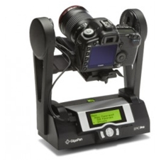 Using the Nodal Ninja 3 panoramic head is a manual process requiring the user to physically move the device to the next image, but this process could be automated using a motorised device, such a GigaPan.
These devices also have the ability to trigger the camera for each image, which would automate the process even more and eliminate taking errors, but the testo 875 used for this investigation did not have the ability to be triggered remotely.
Temperature changes in the scene during the image recording process will show in the resulting panorama and Cube Images.
The time to record the 155 images is around 30 minutes.
Data Processing ~ Creating the Panorama
The recorded images are in the testo BMT format and need to be converted to a format suitable for use with the software that is to be used to create the panoramas (e.g. BMP or JPG). The IRSoft software from testo performs this task, but each image needs to be individually translated and this task takes about 40 minutes for the 155 images (30% longer than recording the images!).
The testo IRSoft software enables the images to be stored in the BMP, JPG or PNG formats, but defaults to BMP each time. Although JPG images are required for the panorama creation software the images were saved in BMP format to reduce the number operations and save time as they can be converted to JPG as part of the next step.
The images converted from the BMT thermal images are upside down, because of the way the testo 875 is mounted on the Nodal Ninja, and have the thermal scale on one side, so the next step is to rotate the images through 180° and crop out the thermal scale. This was done as an automated batch process through Pain Shop Pro X3 and the images saved in the JPG format. Photoshop, and other imaging software, could also be used to perform this task.
The software used to create the panoramas for this investigation was PTGui as this was available, is an industry standard and has powerful functionality which was useful in this investigation.
PTGui uses a two stage process to create the equirectangular panorama from the images.
The first is to “align” the images and one of three processes can be used to achieve this:
1) Use the “Align images…” option to align the images and create the Control Points
2) Create the Control Points manually then Optimise them
3) Use a Template
The low resolution of the thermal images (160 x 120 pixels) rules out method (1), using the “Align images…” option in PTGui, as there simply is insufficient information in the images for PTGui to be able to use its image matching algorithms to achieve the desired result.
Method (2) is impractical as it would take a great deal of time and effort and the low resolution of the thermal images would make it impossible to manually find suitable Control Points in many of the overlaps.
This leaves method (3) and a suitable template was created using the images recorded with the DSLR. When using this method it is vital that the arrangement of the images used to create the template is exactly the same as arrangement of the thermal images. i.e. the order the images are taken in and their directions must be the same.
The second stage is to warp and blend the images into the panorama. For this to be successful the images do need to be of a reasonable resolution with a reasonable amount of information included. The low resolution thermal images meant that if there are areas in the scene with little detail, the resulting panorama will suffer.
The thermal images are not as “sharp” as “normal” photographs because there tends to be a thermal gradient across feature boundaries (e.g. the edge of a window).
The testo logo in these images is also a hindrance to the warp and blend process.
Results
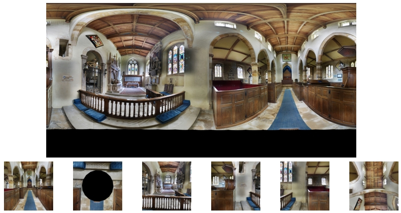
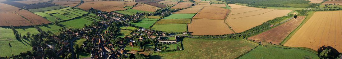
Equirectangular and Cube Images from the “control” images recorded with a DSLR in the Church.
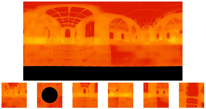
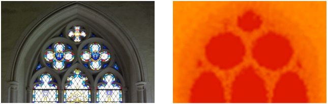
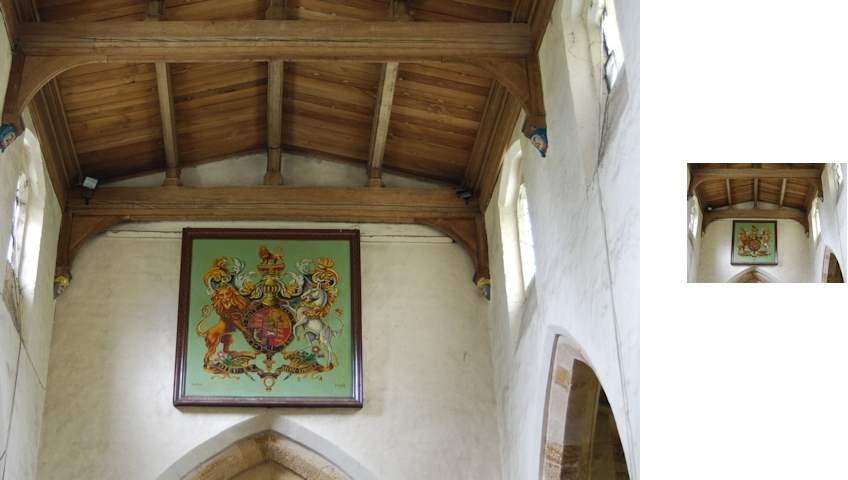
Equirectangular and Cube Images from the testo 875 images in the Church.
The images were “aligned” in PTGui using a template created from the DSLR images and the software has been able to warp and blend the images with a reasonable amount of success. There are some imperfections, especially in the roof area, where there are mismatches between the images.
The temperature scale to the right shows the range set on the thermal camera for the task. This was set before taking the images so that the central horizontal strip would be approximately in the centre of the scale, but the temperature rose during the half hour required to record the images suggesting that the lower tiers of images recorded a warmer area than the horizontal tier. There is only about a 3° temperature range across the final panorama where there was twice this range before starting recording, demonstrating the importance of choosing the right values.
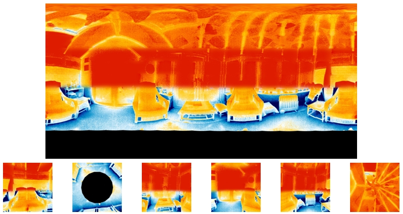
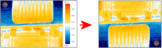
Equirectangular and Cube Images from the testo 875 images in the Sun Lounge.
These images were also “aligned” in PTGui using a template created from the DSLR images but the software has had difficulty in being able to warp and blend the images, especially in the “roof” areas where there is too little detail.
The temperature scale to the right shows the range set on the thermal camera for the task. This was set before taking the images so that the central horizontal strip would be approximately in the centre of the scale, but changes in the temperature during the half hour required to record the images has greatly influenced the result, showing how important getting this aspect right is. Where there is a good temperature gradient and good detail, such as the lower tier images, the results from PTGui are good.
Resolution of Thermal Images
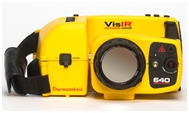 The 160 x 120 pixel format the testo 875 appears to be an “industry standard” (at the time of this investigation), but a scan of the Internet reveals that there are higher resolution thermal imaging cameras and that formats of 320 x 240 pixels and 640 x 480 pixels are available, such as with the VisIR 640.
To investigate the possibility of a 640 x 480 pixel camera producing images that PTGui is capable of “Aligning” without the need for using a template from the DSLR photography, I converted the 32° x 24° DSLR images to both 640 x 480 pixels and 160 x 120 pixels.
The image sizes following, are shown below for comparison.
The 32° x 24° DSLR images (2600 x 1950 pixels) were “Aligned” OK by PTGui and running the Optimizer gave a “good” report with an average Control Point value of 2.59.
The 640 x 480 images were also “Aligned” by PTGui OK, which did prompt for more Control Points to be added manually, but produced a better result than the 32° x 24° DSLR images even without adding any more Control Points. Running the Optimizer gave a “very good” result with an average Control Point value of 1.30! The image in the Panorama Editor was also somewhat better than that produced by the 32° x 24° DSLR images.
The 160 x 120 images could not be “Aligned” by PTGui, which again prompted for Control Points to be added manually, and running the Optimiser gave a “not so good” result with an average Control Point value 0f 18.1, and simply produced a mess in the Panorama Editor.
This would suggest that if further investigation is conducted that a 640 x 480 pixel thermal imaging camera is used.
Hugh Anderson, November 2010.
![]()
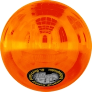 |
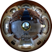
Interactive Thermal Image Panorama of The Church of St Mary | |
 |
For information working with PTGui to create 360° Panoramas with Thermal (Infrared) images, click here or on the image below. | |
 |