Making Use of the Nodal Point
 Using the knowledge of the location of the Nodal Point of a lens will depend on the application. For a Photogrammetric application, such as Photographic Intersection, the displacement (offsets) of the Nodal Point from the centre of rotation of the Instrument on which the camera is mounted is used to derive the point of origin of a ray in space passing through a point digitised in the image. In the case of a lens, such as the Sigma 10-20 mm where the Nodal Point is a single point for a given focal length, the Nodal Point will describe a sphere around the centre of rotation of the Instrument and the displacement is easily applied in the mathematics. If a lens, such as the Nikon 28 mm is used, where the Nodal Point moves along the principal ray depending on the angle of view, then the mathematics is a little more complex. However the first part of the calculation for the point digitised in the image can be used to calculate the angle the ray makes with the principal ray so the correct location of the Nodal Point can be determined.
An application where the location of the Nodal Point is particularly important is in panoramic photography. As discussed in Creating Your Own Panoramas, the location of the Nodal Point is of little interest when taking images for a panorama of scenery which is some distance from the camera, but if the subject is close to the camera or the images are to be used for creating full 360° panorama, then the camera should be rotated about the Nodal Point.
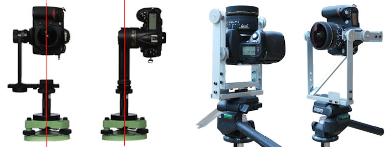
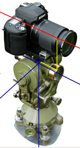
The first consideration is that the camera should be positioned so that the principal ray of the lens coincides with the vertical axis of rotation of the camera. As the Nodal Point(s) lie along the principal ray it (they) will be in the same plane as the vertical axis of rotation, but the camera should then be positioned so that the Nodal Point coincides with this axis. With a lens such as the Sigma 10-20 mm this is easily achieved using a Panoramic Head with the single Nodal Point located at the centre of rotation. Panoramic Heads are available from a number of sources such as Ninja and Manfrotto and range in price and sophistication, the more expensive ones having user settable click stop to accurately position the camera for each exposure. When I first started to explore the world of 360° panoramas I built my own from scraps I had from previous experiments. The advantage was that I had a very light and easily portable panoramic had for very little cost, but the disadvantage was that the head was built around my Nikon D70 and could not be easily modified to accommodate other cameras, so I decided to invest in a Panosaurus. Positioning the Sigma 10-20 mm was straight forward, but the disadvantage of using a rectilinear or ‘normal’ lens in portrait format is the number of exposures required to achieve a good overlap for the software to create the equirectangular image from. As the table following shows, the number of images required rapidly increases as the focal length of the lens increases.
| Creating a full 360° Panorama using a “Normal” Lens in portrait format with an APS-C Sensor | |||||||
| Focal Length | 35mm Equivalent | Number of Directions | Horizontal Angle Sep | Number of Planes | Vertical Angle Separation | Zenith Image | Total Images |
| 10mm | 15mm | 8 | 45° | 3 | 45° | Recommended | 24 |
| 18mm | 27mm | 14 | 25.7° | 4 | 35° | Not required | 56(49) |
| 18mm | 27mm | 16 | 22.5° | 4 | 35° | Not required | 64 (56) |
| 18mm | 27mm | 18 | 20° | 4 | 35° | Not required | 72(63) |
| 20mm | 30mm | 18 | 20° | 7 | 30° | 1 | 127 |
| 30mm | 45mm | 24 | 15° | 9 | 20° | Recommended | 216 |
I usually also take an additional image to the zenith (vertically upwards) which is sometimes useful in the creation of the panorama, especially in situations such as outdoors where clouds in the sky will be in slightly different places for each image.
The above table is only a rough guide as the number of directions can decrease for the planes above and below the horizon if there is plenty of detail in the images. For example; the information for an 18 mm lens is for one plane horizontal, one plane with the camera depressed by 35°, one plane with the camera elevated by 35°, all with 16 directions at 22.5° separation, and a fourth plane with the camera elevated to 70°, but with 8 directions at 45° separation. This is a total of 56 images rather than a theoretical 64 images. It is not necessary to have a plane with the camera depressed by 70° because this “hole” is where the tripod is. The number of directions in the planes with the camera inclined at 35° could also be decreased, but this would take some working out, and software such as PTGui copes with the arrangement as described provided that there is plenty of detail in the overlapping areas of the images, especially between the images at +35° and +70°. However, if there is little detail, such as in a plane room, then it is better to take 16 images at +70° as well.
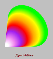
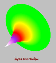 To reduce the number of images a ‘fisheye’ lens such as the Sigma 8 mm or Nikon 10.5 mm can be used, but if we try and visualise the ‘shape’ the rays make inside the lens we can see that the perfect cone of a lens such as the Sigma 10-20 mm is very different to the complex geometry in a lens such as the Sigma 8mm, which is in effect lens distortion. We can position the Sigma 10-20 mm so that the Nodal Point is actually at the centre of rotation of the panoramic head, but where should we position the Sigma 8 mm or Nikon 10.5 mm? Should we position it so that the gold ring is coincident with the vertical axis of rotation, which is where the rays close to the principal ray have their Nodal Points, or should we position it so that that the front of the lens is coincident with the vertical axis of rotation, which is where the rays at the widest angle of view have their Nodal Points, or somewhere in between? I decided to investigate this empirically and found that I could not determine any difference in the results so have settled for “somewhere in between”, but far enough forward to avoid the panoramic head encroaching into the side of the image.
It is worth noting that software, such as PTGui, “warps” the images when creating the panorama and that this “warping” is effectively correcting the image for lens distortion and that such a process usually holds the centre of the image as the starting point (point with no distortion). As the gold ring on both the Sigma 8 mm and Nikon 10.5 mm lenses is located near to where the rays close to the principal ray converge it is a good rule of thumb to position these lenses so that gold ring is coincident with the vertical axis of rotation of the panoramic head.
Note that it is important to position the camera and lens so that the Nodal Point, or the best location for the Nodal Point, is coincident with the vertical axis of rotation of the panoramic head as the results can be unpredictable if this is not the case.
With a fisheye lens, such as the Sigma 8 mm and a full size 35 mm format, the image is a full circle so only three images at 120° intervals are required, plus one to the zenith. With the same lens, in portrait orientation, and an APS-C sensor either six images at 60° intervals or eight images at 45° intervals gives good results. It is possible the ‘get away’ with four images at 90° intervals, but it can be very difficult to get a good result if the overlaps have little or no detail. Taking too many images, such as 12 at 30°, results in too many images having common areas, which can result in a poor solution using software such as PTGui, or even no solution, but in such a case every other image can be excluded and two solution, each of six images, can be achieved. Getting to the site and setting up the camera is the most time consuming part of the exercise so I tend to take two sets, one of six images and one of eight, especially when shooting digitally where the cost of film does not have be taken into consideration . If the tripod in the panoramic image is to be replaced with a “tripod cap” image the camera can be tilted upwards by 10° to 15° so that a zenith image is not necessary, but it is usually worth taking one anyway, especially outdoors where clouds in the sky will be in slightly different places for each image.
An important consideration is that if the fisheye lens does produce a full circle on the sensor, such as with the Sigma 8 mm and a full 35 mm format, that only some 54% if the image is used (i.e. with a 10Mp sensor only 5.4Mp are used) whereas 92% of the image is used with the same lens and an APS-C sensor (i.e. 9.2Mp with a 10Mp sensor ).
A fisheye lens where the 180° angle of view is across the diagonal, such as with a Nikon 10.5 mm lens, fitted to a camera with an APS-C sensor, does result in the whole of the sensor being used. The disadvantage is that such a lens covers less of the subject so that it is advisable to take eight images at 45° intervals although six images at 60° intervals works with this lens if there is plenty of detail in the subject. PTGui also produced good results with the Nikon 10.5mm lens with 12 images at 30° intervals. With the lens horizontal there are quite large “holes” at the top and bottom of the equirectangular and cube images and taking a couple of zenith images was not sufficient because of the limited overlap. If the camera is tilted up by 10° then the zenith images did produce a good result, but with an unacceptable “hole” at the bottom of the resultant equirectangular image. To get the best result with the Nikon 10.5 mm lens I used eight images at 45° intervals with the lens tilted down at -10° and an additional four images at 90° intervals with the lens tilted upwards by 50°.
The table below shows suitable arrangements for creating full 360° panoramas with the Sigma 8 mm and Nikon 10.5 mm lenses.
| Creating a full 360° Panorama using a Fisheye Lens in portrait format with an APS-C size Sensor | |||||||
| First Horizon | Second Horizon | ||||||
| Lens and Focal Length | Vertical Angle from Horizon | Horizontal Angle Sep | Number of Directions | Vertical Angle from Horizon | Horizontal Angle Sep | Number of Directions | Total Images |
| Sigma 8mm | 0° | 60° | 6 | 90° | 90° | 2 | 8 |
| Sigma 8mm | 10° | 45° | 8 | 90° | Recommended | 8 (9) | |
| Sigma 8mm | 0° | 45° | 8 | 90° | 90° | 2 | 10 |
| Nikon 10.5mm | 0° | 45° | 8 | 90° | 90° | 2 | 10 |
| Nikon 10.5mm | 0° | 45° | 8 | 45° | 90° | 4 | 12 |
| Nikon 10.5mm | -10° | 45° | 8 | 45° | 90° | 4 | 12 |
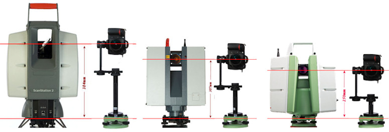
 There are applications where it is important that the Nodal Point coincides with the location of the centre of rotation of another device. HDS (High Definition Surveying) scanners produce a ‘point cloud’ where each point in the image has a 3D co-ordinate, but the colour of the point is determined by the reflectivity of the surface that the point is on. This information is useful in itself, but many users would like to have the ‘true’ colours of the points in the point cloud and this can be achieved by replacing the scanner with the camera on a panoramic head where the Nodal Point of the lens is coincident with the centre of rotation of the scanner and creating a full 360°panorama which can then be related to the scanned points.
 |
||
| Leica ScanStation 2 – 384 mm | Leica HDS6100 – 307 mm | Leica ScanStation C10 – 250 mm |
![]()