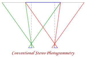
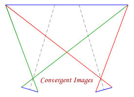
 Stereo Photogrammetry benefits from the use of wide angle lenses to get the best coverage and to ensure that the rays to the discrete points intersect with the best geometry. For a single stereo pair with 60% overlap, 40% of each image is not usable. This can be overcome by using convergent images, but viewing and extracting data from these becomes troublesome, which leads on to the idea of Photographic Intersection.
To extract data from conventional stereo images three orientations are required. Inner Orientation is the reconstruction of the camera geometry and the correction of lens distortion. This is followed by the Relative Orientation to obtain the relationship between the two images forming the stereo model utilising common points in the two images. Control points in the model are then used to perform the Absolute Orientation to bring it into the required co-ordinate system, which is in effect a resection for the location and orientation of the camera positions.
With Photographic Intersection the Inner Orientation is still required as the camera geometry needs to be known and the Relative Orientation is now the relationship between the camera and the Theodolite or Total Station on which the camera is mounted. The Absolute Orientation is derived from the known location and orientation of the Theodolite or Total Station and the other two orientations, giving a more precise and accurate result than that used in conventional stereo photogrammetry.
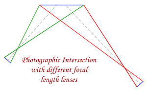 With modern digital cameras the Inner Orientation process can be improved by using software packages such as DxO and PTLens. These packages use the information from the exif data contained in the digital image, together with lens characteristic information for the camera and lens combination, to correct the digital image for lens distortion. In the past zoom lenses have been considered as unsuitable for photogrammetric data extraction because the lens characteristics change with the changes in focal length, but as this can now be easily accommodated with software such as DxO and PTLens, zoom lenses are ideal for Photographic Intersection as the focal length best suited to cover the subject can be selected. The use of different focal lengths for Photographic Intersection enables situations with difficult access to be measured.
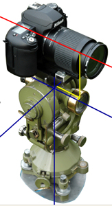 The relationship between the camera and the theodolite on which it is mounted can be considered as the difference in location of the front nodal point of the lens and the intersection of the theodolite trunion axis with that of the telescope. The computation of the co-ordinates for the front nodal point of the lens is from the location and orientation of the theodolite together with the three components representing the linear, lateral and offset of the nodal point. Even if the theodolite telescope was replaced by the camera there would still be a linear separation between the ‘centre’ of the theodolite and the front nodal point of the lens. Such a device was prototyped by Leica Geosystems in 2001 and would have been ideal for Photographic Intersection.
In theory the orientation of the camera principal ray will be parallel to the axis of the theodolite telescope. However, this is unlikely to be the case for the precision required, but correction for misalignment can easily be accommodated as part of the operating procedure and computation of the data. For Photographic Intersection it is necessary to orientate the theodolite to a known point. Preferably orientation is established by observing a known point and checked by observing another known point after taking the images. 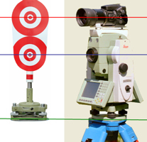 The target used at these points consists of two targets separated by the difference between the theodolite telescope axis and the camera principal ray. The lower target is bisected with the theodolite crosshairs and a photograph taken. The upper target is digitised in the image and its pixel co-ordinates used as the reference for the principal ray of the camera rather than using the centre of the image.
 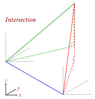 This gives a point in the image for which the origin and orientation in space is know. Any other points in the image can now be digitised and its origin and orientation in space calculated using the Inner Orientation information and the pixel co-ordinates. When the same point of detail is digitised in the second image the two rays, which both now have known origin and orientation can be used to calculate the 3D co-ordinates for the point of detail by intersection. If the same point can be digitised in a third or subsequent image, the calculations will give an indication of the precision of the 3D co-ordinate value and an improved solution.
 The rapidly increasing concentric circles target was developed by David Stevens and myself in 1980, when we we working for BKS Surveys, as the ideal target for close range photogrammetry as it could be accurately bisected by the theodolite cross-hairs, a floating point or cursor, even if the target was acutely oblique to the observer. The red and white colours were chosen as they provided excellent contrast, especially when we used black and white film, and did not blank out the theodolite cross-hairs as black would have done.
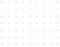
If film, or a digital camera, for which there is no lens information is being used to record the image, calibration of the lens at a particular focal length can be determined by photographing a ‘calibration chart’ and calculating the values for correction in the different parts of the image and these ‘calibration values’ can be applied to the digitised pixel co-ordinates prior to calculating the origin and orientation of ray in space.
 There is another source of error that needs to be considered. If the camera is not level then the rotation of the camera will have to be ‘corrected’ for before any further computation is made. It is probably easier to ensure that the camera is correctly mounted on the theodolite, as is the case with the Wild P30 Photo Theodolite and Wild P32 Camera mounted on a theodolite, than apply a rotation correction to the image. The rotation of the camera can be easily be examined by photographing an horizontal line, such as the horizon of the sea, or by photographing a ‘target’ point with the point at the centre for one image, extreme left for another and extreme right for a third. The three images can then be complied into a single image, but in three different layers in Photoshop or Paint Shop Pro, and the erase tool used to remove the relevant parts of the layers so that all three position of the point can be seen together.
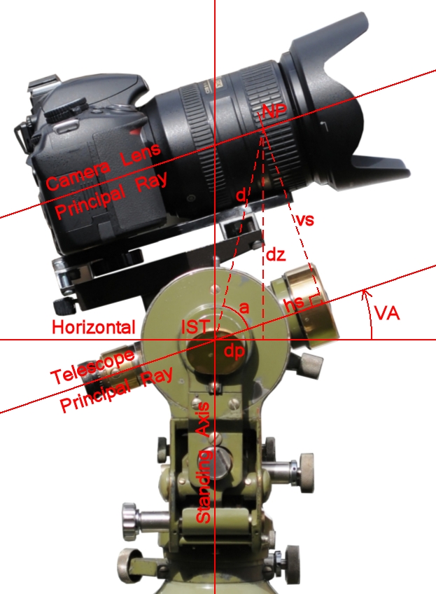
To enable the correct origin and orientation in space of the rays used to compute the intersection it is important that the Nodal Point of the lens is determined as accurately as possible. The front Nodal Point of the lens can be considered as the point at which the rays entering the lens converge and is the ideal point to rotate your lens around when taking images to ‘stitch’ together to produce panoramic images. There is also a rear nodal point, and in a simple lens the two nodes converge to a single point.
![]()
The displacement of the Entrance Pupil of the camera lens and the intersection of the Standing and Trunion axes of the theodolite is corrected for using basic trigonometry.
If the co-ordinates of the intersection of the Standing and Trunion axes are X Y Z, then the co-ordinates of the Nodal Point (x y z) are calculated as follows:
tan a = vs / hs
d = square root ( vs2 + hs2 )
z = Z + dz = Z + d ( sin ( VA + a )
dp = d ( cos ( VA + a ) )
vs = Vertical Separation between the two Principal Rays
hs = Horizontal Separation between the NP and IST
NP = Null Point (Entrance Pupil) of the camera lens
IST = Intersection of the Standing and Trunion Axes
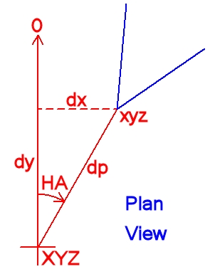
If the camera/lens axis is misaligned with the with the theodolite axis horizontally this can be corrected for as follows:
x = X + dx = X + dp ( sin HA )
y = Y + dy = Y + dp ( cos HA )
![]()