When I published this page I used the title “Finding the Nodal Point of a Lens” as it was the parlance for the time the page was published. Today the term No Parallax Point (NPP) is a more suitable option, although another option suggest by Michel Thoby could also be considered as a more accurate term for our “point of interest”, the Least Parallax Point (LPP) as in many (probably most) lenses, especially fisheye lenses, the “point of interest” varies with the angle the incoming ray makes with the principal ray of the lens.
The No Parallax Point (NPP) or Entrance Pupil can be considered as the point at which the rays entering the lens converge. It can also be considered as the centre of perspective of the lens or the apparent pupil.
It is important to know the location of this point (NPP) for Photogrammetric purposes. To enable the correct origin and orientation in space of the rays used to compute the intersection when using the technique of Photographic Intersection it is important that this point is determined as accurately as possible. It is also vital that this point is known for applications such as using the photographic image in conjunction with HDS (High Definition Surveying) data and for any application for where an equirectangular image is to be produced using software such as PTGui.
The Left Image is rotated about the ‘Tripod Bush’ and the Right Image rotated about the NPP
 This point is the ideal point to rotate your lens around to eliminate parallax when taking images to ‘stitch’ together to produce panoramic images, especially 360° Panoramas. If you are creating a panorama of objects very close to the camera then serious consideration needs to be given to this point to eliminate parallax as shown in the image to the right, but if your panoramas are of features tens or hundreds of metres from the camera, such as a landscape panorama, then you will not need to give too much thought to this point.
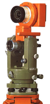
Photogrammetric camera lenses are constructed so as to be ‘symmetrical’. The mounting of the Wild P32, shown in the image to the right, on a theodolite was arranged so that the front Nodal Point (NPP) of the lens was coincident with the standing axis of the theodolite when the telescope was truly horizontal even though this meant that the camera was not well balanced. In normal photographic lenses, such as those we would select for Photographic Intersection, this point is often not a single point but ‘slides’ along the principal ray of the lens depending on the angle between the ray being considered and the principal ray. For the purposes of Photographic Intersection the position of these points should be determined for the widest angle of view for the lens, although there is the opportunity to introduce the different locations as another parameter in the computation process.
April 2007
Finding the location of the No Parallax Point (NPP) (Entrance Pupil)
The NPP can be measured as part of the camera and lens calibration process using a calibration rig constructed for determining the parameters of the camera and lens for photogrammetric purposes. Such setups are few and far between, and even if you do locate one, the cost of the calibration will probably be more than the value of the equipment you are calibrating, which defeats the object of using Photographic Intersection as a low cost method of accurately measuring 3D points. It is therefore desirable to find a way of determining the NPP yourself with easy to obtain and low cost items.
 At the end of the 1970s, beginning of the 1980s, I used a method similar to that described by Michel Thoby except that I used needles and the face of an “E” survey staff or tape measure.
The important thing is that the foreground objects do not obscure too much of the background and that the background has sufficient detail to identify accurately the part obscured in the image by the foreground objects.
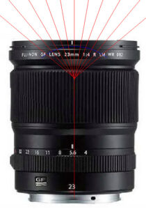
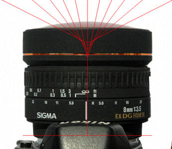
 The technique is to make an image of the scene, then use the detail of the background object obscured by the foreground objects to reconstruct the rays that converge at the NPP and thus define it. It is imperative that nothing in the arrangement must be disturbed whilst a suitable print of the scene is made so that the rays can be accurately drawn. In the digital age this is not so much of a problem but when film is used keeping the scene intact can be a problem. A disadvantage of this method is that using nails or needles with a background quite near to the lens is that the lens is close focused to keep the detail sharp in the image, but that the lens will more likely to be focused at or near infinity when actually used for measurement. The NPP can change with focusing in some lenses. This can be overcome by going outside and using canes, ranging rods or dowels as the foreground objects with say a building facade as the background image and with the camera and lens on a “Plane Table”. Keeping the arrangement undisturbed whilst processing film and printing a decent size image was even more of a challenge! Note that the camera has been rotated around its principal ray so that the diagonal of the field of view is used to get the maximum angle of view, a technique that can be used with both the other methods following.
![]() As we are now well and truly in the ‘digital age’ this method is less trouble than in the age of film as the positions of the camera, ‘pins’ and ‘target’ (e.g. tape measure) can be accurately measured and and imported into a CAD application where the ‘rays’ can then be ‘drawn’ and their intersection with the principal ray determined.
As we are now well and truly in the ‘digital age’ this method is less trouble than in the age of film as the positions of the camera, ‘pins’ and ‘target’ (e.g. tape measure) can be accurately measured and and imported into a CAD application where the ‘rays’ can then be ‘drawn’ and their intersection with the principal ray determined.
This method is suitable for cameras with a tiny or no view screen, such as dual and multi lens cameras.
April 2007
A simple method …
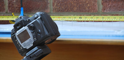
A simpler method of determining the NPP is to place an object (thin pole or wire) near the lens and align it with a more distant object. If the camera is rotated about the NPP the two objects will be aligned when they are in the centre of the image and also when at each side of the image. If the objects are aligned when in the centre of the image but appear to separate as the camera is rotated then the rotation is not about the NPP. This method may be simpler than the first method described, but is more fiddly and less accurate.
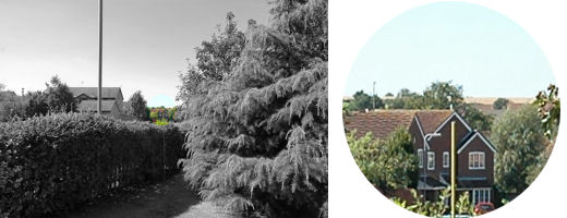 To determine the NPP of a Nikon 18-70 mm zoom lens set at 18 mm, a 10 mm dowel was positioned some 7 m in front of the camera so that it was aligned with the apex of the roof of a house some 200 m away. The camera was rotated around the tripod mounting point in the base, which is behind the NPP, and a point a similar distance in front of the NPP to illustrate the apparent movement of the dowel relative to the roof apex if the camera is not rotated about the NPP.
 |
 |
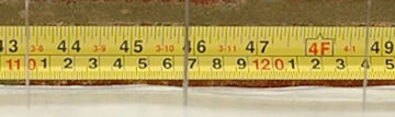
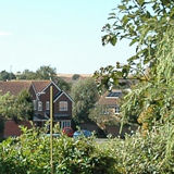
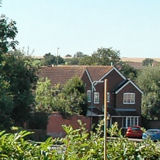
When the camera is rotated about the NPP the dowel is still aligned with the apex of the roof of the house at both the Left and Right edges of the image. Note that this is at the NPP for that particular angle of incidence if the lens does not have a single point for the NPP as in some of the examples following. |
 |
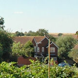 |
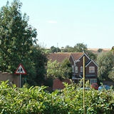
In this case the camera was rotated about the tripod mounting point, which is behind the NPP. This is the normal case for a camera mounted on a tripod using the ¼” Whitworth thread in the camera’s base plate. |
 |
|
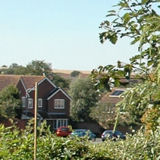
To show the effect of the rotation of the camera in front of the NPP the camera was mounted on a bar so that the rotation point was approximately as far in front of the NPP as the ¼” Whitworth thread in the camera’s base plate is behind the NPP. |
April 2007
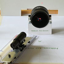
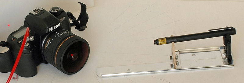
 An innovative and inspired method I have come across (June 2007) is that used by Michel Thoby with a Laser Pointer. As Michel states, you only need the lens for this method. However, having the lens mounted on a film camera with the shutter open on bulb and the back open means that you can calibrate any lens as the lens axis will always be the same height above the surface. This means that it is easier to construct your laser alidade with a fixed height for the laser above the surface. When the laser beam travels along the path of a ray that meets the NPP, a very bright spot is seen on the surface (white card) placed behind the lens and the ray can be drawn on the paper. These rays can be constructed for a variety of angles of incidence and the NPP determined.
This method is remarkably precise and accurate results can be obtained quickly and easily. The position of the lens, especially the front which will be used as the reference, can be orthographically projected onto the paper using a simple set square.
Laser pointers are readily available from outlets such as Amazon and ebay, but my experience with these is that the laser beam is not accurately aligned with the barrel and that the switch has to be held to keep the laser on. The later can be solved by holding the switch down with tape, but the misalignment of the laser is more challenging. Laser gun sights can also be purchased from outlets such as Amazon and ebay for not much more and have the advantage of a regular on off switch and the laser can be adjusted to align with the barrel making it more suitable for determining the NPP.
Laser safety: When using lasers ensure that they are used in a safe manner and always follow the manufacturer’s safety instructions.
June 2007
 An inspired innovation for using a laser to determine the NPP (No Parallax Point, Entrance Pupil or Nodal Point) of a lens has been posted by Garry George. Using a laser with a line has a distinct advantage over using a laser with a dot which requires the laser beam and principal ray of the lens to be in the same plane which would normally be a horizontal plane with the laser and principal ray the same height above the base surface. Using a laser line as obtained with a Cross Line Laser means that this is no longer necessary making the process easier.
The method using a Cross Line Laser is very much the same as using a Laser Pointer as only the lens is required and when the laser passes through the NPP the image projected behind the lens is maximised and the ray can be drawn on the paper. These rays can be constructed for a variety of angles of incidence and the NPP determined for the required application.
Accurate results can be obtained quickly and easily using a Cross Line Laser. The position of the lens, such as the front if it is used as the reference, can be orthographically projected onto the paper using a simple set square.
When laser devices were first introduced they were expensive reflecting the cost of development, but over the years prices have dropped considerably and today the cost a Cross Line Laser is not much more than an Adjustable Laser Gun Sight or even a Laser Pointer making determining the NPP of a lens using a Cross Line Laser an attractive option.
Laser safety: When using lasers ensure that they are used in a safe manner and always follow the manufacturer’s safety instructions.
December 2024
Finding the No Parallax Point without a Panohead …
Setting up a laser is time consuming and fiddly but another method proposed by Michel Thoby more recently provides a simpler solution.
The camera and lens is placed on a sheet of paper as with the method of using a laser pointer but this is replaced with a ‘target’ which is essentially a ruler with two thin vertical sighting vanes.
This device is placed in front of the lens and rotated until the two vanes line up when viewed through the viewfinder or on the ‘live screen’ of the camera and a line drawn on the paper along the straight edge connecting the two vertical vanes.
This is repeated for different ‘angles’ building up a diagram of the pattern of rays entering the lens and the NPP is determined by where the lines intersect with the ‘principal ray’ of the lens.
The position of the lens, especially the front which will be used as the reference, can be orthographically projected onto the paper using a simple set square.
I found this method quite difficult sighting the ‘target’ with the viewfinder or on the ‘live screen’, especially with finding the NPP for Fisheye lenses for 360° Panoramas. Also, this method would not be suitable for finding the NPP of dual or multi lens cameras with tiny or no view screen so I decided to modify this method with the principal of the ‘simple method’.
A simple method – modified …
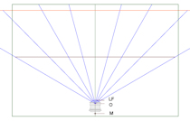
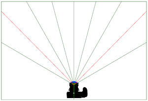 A straightforward method to determine the NPP of Fisheye lenses, including those on dual or multi lens cameras with tiny or no view screens, is to plot the rays on paper radiating from a reference point. The camera is then positioned so that front of the lens is coincident with this
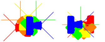
 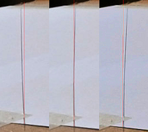 reference point. Images are then captured moving the camera forward two millimetres at a time ensuring that the camera is moved sufficiently to ensure that the NPP will be covered. The images can then be viewed comfortably on a computer and the NPP for a particular angle of incidence can be determined by the distance in front of the lens where the line drawn on the paper is vertical in the image. Typically the NPP is not a single point, as shown in the examples, so for 360° Panoramas I select the NPP for the ‘join’ angle for stitching the images (e.g. 45° from the principal ray for 4 shots round and 30° from the principal ray for 6 shots round). If this is the case then it is only necessary to plot the required rays on the paper. The image to the left shows screen captures at 250% of the position for a Pergear 7.5 mm Fisheye lens for the 45° ray at 2 mm intervals in front of the reference point at the front of the lens with vertical red lines superimposed so it is easy to locate the NPP at say 45° (4 shots round) for this lens.
![]()