Differential GPS Measurements for Gravity Survey
Introduction
A primary science activity for the Survey Fire was to provide accurate height information for a Gravity Meter Survey to be conducted by the Geosciences Fire. In the event, both Fires worked together on this project.
The most important consideration was the required accuracy of height measurements. The Gravity meter measures the pull of gravity and the last count on the dial is equivalent to a mere 0.03 metres in height, although accurately reading this is extremely tricky, so we needed to achieve relative heights between successive gravity reading of better than 0.1 metres with 0.03 metres as the goal.
This level of height accuracy is achievable using the more traditional methods of Spirit Levelling or Trigonometrical Heighting with a Theodolite but is also achievable using the more modern method of GPS (Global Positioning System) using Survey GPS rather than Navigation GPS. Both Spirit Levelling and Trigonometrical Heighting are very time consuming when compared with GPS measurements and would conflict seriously with the logistics of the expedition, so GPS was chosen. In order to achieve required height accuracy the technique of DGPS (Differential GPS).
The difference between Navigation and Survey GPS
Navigation GPS receivers use a Code transmitted by the GPS satellites to calculate the position on the earths surface. The precision of the position fix using Navigation GPS is to tens of meters as detailed in a subsidiary report. In order to achieve centimetre accuracy, Survey GPS receivers use the signal carrier wave from the GPS satellites. This does not provide a position fix, but if two receivers are collecting data simultaneously, at each end of a line (base line), the vector (differences) between the two receivers can be calculated to this high level of precision. The assumption is that both receivers have the same errors caused by the signals passing through the Ionosphere and the Atmosphere, especially if they are relatively close together (i.e. 10 to 20 Kilometres apart). Absolute position can be determined using Survey GPS by relating the data back to a base line with one receiver on a “known” point.
Methodology
DGPS involves the simultaneous collection data by two or more Survey GPS receivers with the “corrections” being related to one of the receives, called the base station. This can be done in “real time” using a technique known as RTK (Real Time Kinematic) GPS where the base station transmits the “corrections” to the other receiver(s) by radio or GSM phone, or the data can be collected and post processed. The advantage of working with RTK is that as soon as sufficient data has been collected to resolve the ambiguities (see the end of this report) the survey team can move on, but the disadvantage is that additional equipment (e.g. radios, batteries, etc.) is required in the field adding to logistical considerations, especially with battery charging and radio reception. The disadvantage of collecting data for post processing is that the GPS receivers have to be recording data simultaneously for enough time for the users to be sure that there is sufficient data to resolve the ambiguities at the processing stage. This method fitted well with the expedition logistics as the gravity meter readings themselves required a similar time to that needed to be sure that sufficient GPS data had been collected. The general rule of thumb is two minute for each Kilometre between the receivers and the base line lengths were envisaged to be around 10 Km making occupation time of around 20 minutes, which worked in well with the gravity meter reading times.
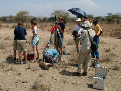 The GPS and Gravity Meter data is collected simultaneously.
Equipment
The choice of equipment was two Leica SR530 receivers with lightweight aluminium tripods. These Leica GPS SR530 receivers proved their worth in this harsh environment and worked faultlessly throughout the expedition despite the heat and dust. The Young Explores were inexperienced in the use of Survey GPS equipment, having not seen any until they actually arrived in Tanzania, but were able to operate it and achieve excellent results with tuition on-site.
The data was processed using the LGO (Leica Geo Office) software.
Absolute Position on the Earths Surface
The DGPS data provided accurate relative positions for all the points measured during the expedition. Although these positions could be related to their location on the earths surface by using the Navigated positions determined as part of the data collection process a more accurate result was desired. These could be achieved by computing the data collected during the expedition in conjunction with data collected simultaneously at ISG Earth Stations. These ISG Earth Stations collect GPS data at points on the earth’s surface with locations determined to great precision by a variety of techniques including GPS. The data can be accessed through the Internet and used to process GPS base lines in the same way as the used to calculate the GPS base lines measured during the expedition.
Four primary locations were selected at the camp sites at Longido, Kitumbeine, Lengai Base and Kerimasi Base and these were occupied for up to 12 hours.
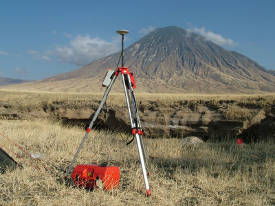 One of the Primary Base GPS Station was at Kerimasi Base camp with Ol Doinyo Lengai dominating the horizon.
The data from three ISG Earth Stations was downloaded. These were based at Malindi on the Kenyan coast, Mbarara in Uganda and Mahe in the Seychelles. The LGO software has a limit of 400 Km for resolving base lines and Malindi was the only Earth Station in this range so all calculations related back to this ISG Earth Station. The data from Mbarara and Mahe was used to check the results from the Malindi calculations and used as a guide to determine the accuracy of the calculations.
The data for Malindi and Mahe was good data, but Mbarara had been experiencing difficulties so the results were provisional and only accurate to some 0.3 metres, but this still provided a good check on the results from Malindi. Had the data from Mbarara been good it would have been a useful Earth Station to use, as its altitude was similar to the points surveyed during the expedition, whereas Malindi and Mahe are at sea level which means that the GPS signals had an additional Kilometre of atmosphere to pass through.
The positional information for the ISG Earth is typically displayed as:
33201M001 MALINDI GPS MALI 4865366.487 4110737.445 -331121.710
39801M001 MAHE ISLAND GPS SEY1 3602870.766 5238174.329 -516275.514
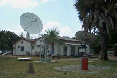 The GPS receiver at the ISG Earth Station at Malindi on the Kenyan coast is located on the red concrete pillar to the right of the photograph.
Results
Whilst collecting the GPS data a pattern of “check bases” and “closed traverses” we were used so that it was possible to establish that the precision of the results. These showed that they were better than 0.1m in both plan and height with many of the points showing much better results than this, so we achieved our goal in an efficient manner.
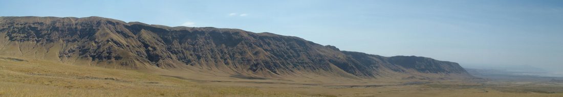
During the course of the expedition the Leica SR530 receiver, aluminium tripod and gravity meter were backpack packed to some very difficult locations. Not only was it taken to the top of Ol Doinyo Lengai and used to traverse down its precipitous flanks but it was also taken up the western wall of the Rift Valley, by way of Laws Ridge, to the complete the gravity traverse across the valley floor.
The Gravity Meter and GPS points followed the route taken by the expedition across the floor of the Rift Valley starting at Longido in the east across to the region around Ol Doinyo Lengai. The primary Stations to relate back to the ISG Earth Stations were at Longido, the easternmost point, Kitumbeine, the southernmost point, and Kerimasi and Lengai base camps in the west.
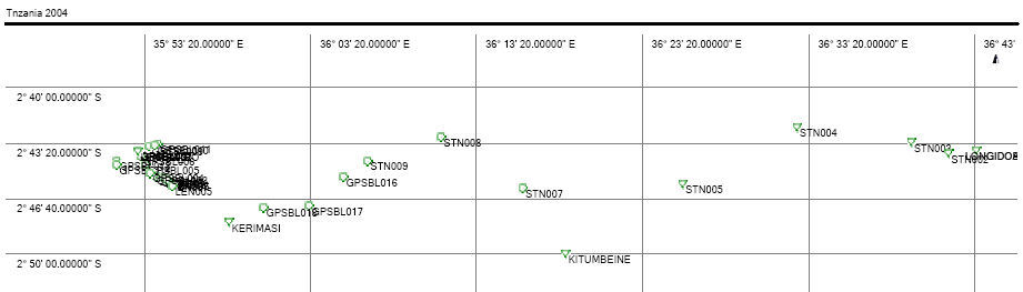
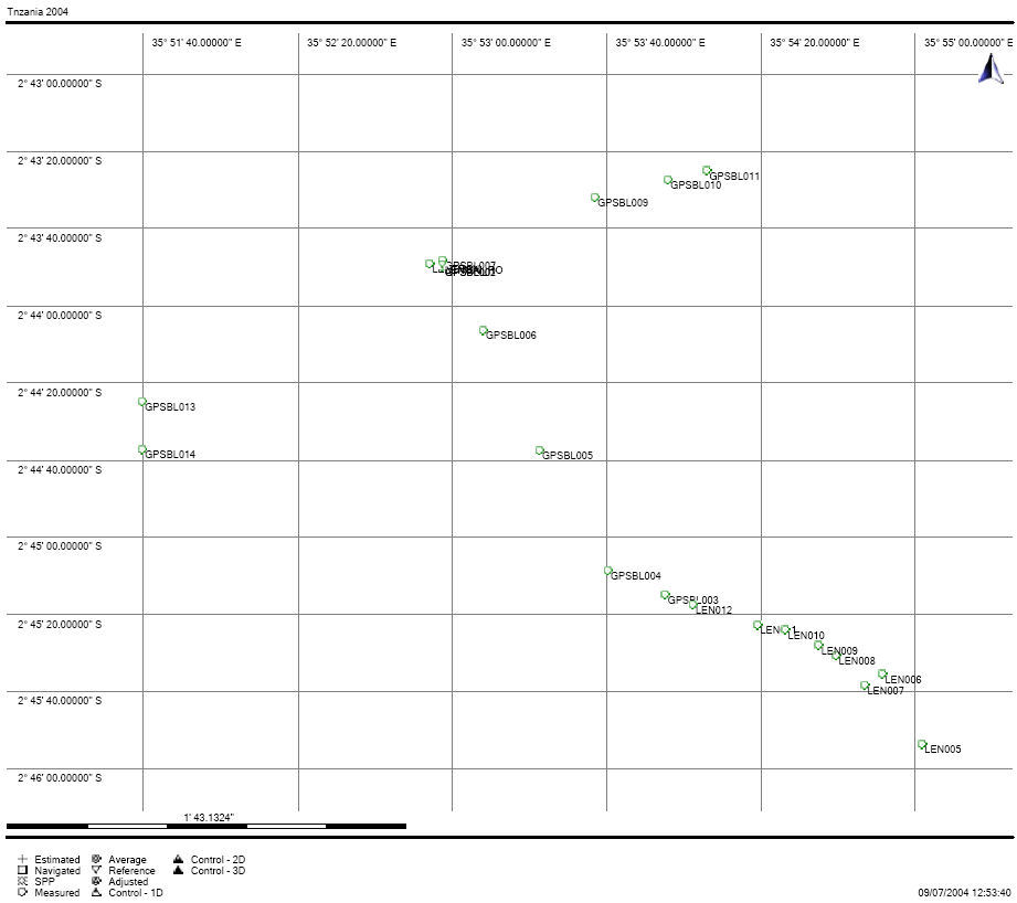
As Ol Doinyo Lengai was the focus of the expedition, a greater density of points were recorded in this location. Points were measured down the flank of the volcano, and the two westernmost points at the top of the western wall of the Rift Valley.
The data collected from the four primary GPS Stations were first computed to the ISG Earth Station at Malindi to establish their absolute location on the earth’s surface. Check computations were also made to the ISG Earth Stations at Mbarara and Mahe and these agreed to 0.3 metres in plan and height with the values obtained from the calculations to Malindi.
The base lines observed during the expedition were computed using these four primary stations as the reference stations. Using check measurements and common points the precision of the survey was determined to be better than 0.1 metres in both plan and height.
Bearing in mind that ambiguities were only resolved to the ISG Earth Station at Malindi and not to those at Mahe or Mbarara, the overall precision of the absolute locations of the GPS points measured during the expedition was achieved to 0.1 metres in plan and height, which was the desired result for providing information for the Gravity Meter survey and for related studies of investigating the accuracy of a Navigation GPS determination and calculating the height of Ol Doinyo Lengai.
Position in Degrees, Minutes and Seconds for the points determined by DGPS
| Point | Type | Date | Latitude S | Longitude E | Height |
| LONGIDOA | Reference | 07/19/2004 09:00 | 2° 43′ 46.65576″ S | 36° 43′ 27.08642″ E | 1342.88 |
| LONGIDOB | Averaged | 07/19/2004 06:12 | 2° 43′ 46.62238″ S | 36° 43′ 27.05667″ E | 1342.98 |
| STN002 | Reference | 07/21/2004 09:45 | 2° 43′ 56.24684″ S | 36° 41′ 44.03650″ E | 1326.90 |
| STN003 | Reference | 07/21/2004 10:55 | 2° 43′ 15.75038″ S | 36° 39′ 30.96916″ E | 1317.45 |
| STN004 | Reference | 07/21/2004 12:19 | 2° 42′ 21.62493″ S | 36° 32′ 39.33202″ E | 1427.09 |
| STN005 | Reference | 07/21/2004 13:41 | 2° 45′ 48.85434″ S | 36° 25′ 44.33227″ E | 1268.15 |
| KITUMBEINE | Reference | 07/22/2004 07:43 | 2° 50′ 00.50408″ S | 36° 18′ 42.19313″ E | 1200.51 |
| STN007 | Measured | 07/22/2004 08:36 | 2° 46′ 02.01005″ S | 36° 16′ 07.52006″ E | 1082.77 |
| STN008 | Measured | 07/22/2004 10:15 | 2° 42′ 55.32037″ S | 36° 11′ 12.96449″ E | 1031.68 |
| LEN005 | Measured | 07/30/2004 05:24 | 2° 45′ 53.56600″ S | 35° 55′ 01.68902″ E | 2804.40 |
| LEN006 | Measured | 07/30/2004 06:42 | 2° 45′ 35.30156″ S | 35° 54′ 51.34849″ E | 2818.59 |
| LEN007 | Measured | 07/30/2004 07:14 | 2° 45′ 38.27198″ S | 35° 54′ 46.89467″ E | 2802.67 |
| LEN008 | Measured | 07/30/2004 08:29 | 2° 45′ 30.70083″ S | 35° 54′ 39.46206″ E | 2709.24 |
| LEN009 | Measured | 07/30/2004 09:38 | 2° 45′ 28.03403″ S | 35° 54′ 34.88932″ E | 2594.46 |
| LEN010 | Measured | 07/30/2004 10:36 | 2° 45′ 23.84674″ S | 35° 54′ 26.26206″ E | 2409.58 |
| LEN011 | Measured | 07/30/2004 11:15 | 2° 45′ 22.59607″ S | 35° 54′ 19.01902″ E | 2261.07 |
| LEN012 | Measured | 07/30/2004 12:13 | 2° 45′ 17.40242″ S | 35° 54′ 02.42677″ E | 1944.18 |
| LENTRAN | Measured | 07/31/2004 07:13 | 2° 43′ 48.97792″ S | 35° 52′ 54.20871″ E | 1107.61 |
| GPSBL001 | Measured | 07/31/2004 12:26 | 2° 43′ 49.83288″ S | 35° 52′ 57.44591″ E | 1107.67 |
| GPSBL002 | Measured | 07/31/2004 12:31 | 2° 43′ 49.83287″ S | 35° 52′ 57.44599″ E | 1107.68 |
| GPSBL003 | Measured | 07/31/2004 19:22 | 2° 45′ 14.73348″ S | 35° 53′ 55.05897″ E | 1841.07 |
| GPSBL004 | Measured | 07/31/2004 20:07 | 2° 45′ 08.57603″ S | 35° 53′ 40.30068″ E | 1649.55 |
| GPSBL005 | Measured | 07/31/2004 20:59 | 2° 44′ 37.40312″ S | 35° 53′ 22.52740″ E | 1348.63 |
| GPSBL006 | Measured | 07/31/2004 21:41 | 2° 44′ 06.36231″ S | 35° 53′ 07.90498″ E | 1174.21 |
| GPSBL007 | Measured | 08/01/2004 06:03 | 2° 43′ 48.20376″ S | 35° 52′ 57.35539″ E | 1103.56 |
| LENGAI_RO | Measured | 08/01/2004 06:24 | 2° 43′ 49.23083″ S | 35° 52′ 57.52020″ E | 1106.74 |
| GPSBL009 | Measured | 08/02/2004 06:44 | 2° 43′ 31.73961″ S | 35° 53′ 36.96484″ E | 1063.00 |
| GPSBL010 | Measured | 08/02/2004 07:45 | 2° 43′ 27.27959″ S | 35° 53′ 55.97718″ E | 1058.87 |
| GPSBL011 | Measured | 08/02/2004 08:28 | 2° 43′ 24.92299″ S | 35° 54′ 05.99968″ E | 1053.18 |
| GPSBL013 | Measured | 08/03/2004 05:47 | 2° 44′ 24.69355″ S | 35° 51′ 39.53965″ E | 1708.63 |
| GPSBL014 | Measured | 08/03/2004 07:00 | 2° 44′ 37.11617″ S | 35° 51′ 39.72796″ E | 1731.14 |
| KERIMASI | Reference | 08/05/2004 07:27 | 2° 48′ 04.96857″ S | 35° 58′ 25.64845″ E | 1029.98 |
| GPSBL016 | Measured | 08/05/2004 09:55 | 2° 45′ 20.32756″ S | 36° 05′ 18.27383″ E | 1018.57 |
| GPSBL017 | Measured | 08/05/2004 11:16 | 2° 47′ 05.26248″ S | 36° 03′ 14.04968″ E | 915.09 |
| GPSBL018 | Measured | 08/05/2004 12:45 | 2° 47′ 13.52203″ S | 36° 00′ 29.33248″ E | 946.62 |
| LENGAI | Reference | 09/06/2004 11:12 | 2° 43′ 49.24388″ S | 35° 52′ 57.48465″ E | 1106.74 |
| STN009 | Measured | 09/06/2004 11:27 | 2° 44′ 22.39308″ S | 36° 06′ 45.41933″ E | 1103.43 |
| GM1 | Measured | 07/31/2004 | 2° 43′ 45.78896″ S | 35° 52′ 53.26600″ E | 1106.58 |
| GM2 | Measured | 07/31/2004 | 2° 43′ 40.58746″ S | 35° 53′ 10.03887″ E | 1084.45 |
| GM3 | Measured | 07/31/2004 | 2° 43′ 37.77218″ S | 35° 53′ 22.07219″ E | 1084.59 |
| GM4 | Measured | 07/31/2004 | 2° 43′ 48.47234″ S | 35° 52′ 41.30072″ E | 1090.99 |
Ellipsoid and Orthometric Heights
The surface of the earth is not a truly mathematical shape so is approximated to an ellipsoid which is a mathematical figure formed by rotating an ellipse about one of its axis. In the case of the earth, the shortest (north south) axis is used.
Ellipsoidal heights are the heights above this theoretical figure and are the values determined by GPS observations as these are related to an ellipsoid. To complicate the matter further, different ellipsoids are used for different parts of the earths surface to get the “best fit”.
 Orthometric heights are heights above the Geoid. The Geoid is the true shape of the earth and is described as the equipotential surface best fitted to mean sea level. This is a surface where the pull of gravity is the same for all points on the earths surface. As there are an infinite number of such surfaces, the one closest to mean sea level is chosen.
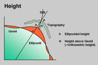
The difference between Ellipsoidal and Orthometric heights.
h = the height of P above the Ellipsoid, shown in green.
H = the height of P above the Geoid, shown in orange.
As can be seen from the data the difference between the Geoid and the Ellipsoid in the region surveyed is only around 10 metres. This varies around the globe in the United Kingdom the Geoidal Separation, as it is called, is some 50 metrers.
DGPS
Differential GPS has a high relative accuracy.
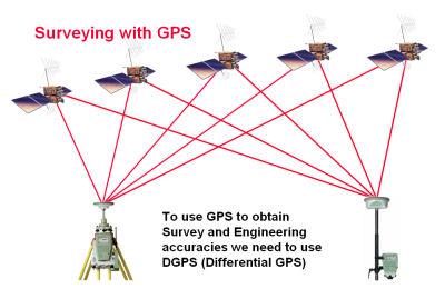 GPS data is collected simultaneously at both ends of a line providing the difference in co-ordinates between the two points rather than the actual location of a single point.
Ambiguity Resolution
Survey accuracy GPS uses the phase difference in the carrier wave from the GPS satellites. The phase difference at each receiver can be measured, but the “unknown” is the number of whole cycles of the carrier waves. As the satellites move across the receivers of field of view the change in number of whole cycles as well as the phase differences can be recorded. The “ambiguity” that needs to be resolved is the number of whole cycles.
In theory, position is three “unknowns”, x, y and z, so in theory the data from three satellites is required to resolve these ambiguities. However, despite the use of high precision time keeping devices, actual time is also an unknown so a minimum of four satellites is required. The data observed simultaneously by each receiver from a minimum of four satellites is used to resolve the ambiguities by the method of least squares.
Seen from the data the difference between the Geoid and the Ellipsoid in the region surveyed is only around 10 metres. This varies around the globe in the United Kingdom the Geoidal Separation, as it is called, is some 50 metrers.
![]()