The development of the 360° Panoramic Optic for Photographic Intersection
The productivity of using photography as a measurement tool really manifested itself in 1973 when I was required to map Annesley Hall (north of Nottingham) in its entirety at a scale of 1:50. The building was a myriad of rooms. There was a cellar and four floors with mezzanine floors between and the roof space and roofscape to map. The nature of the building meant that the rooms were not rectangular and the walls were not parallel. Also, there were many hidden spaces including priest holes and a completely sealed off room above the main entrance. It was also a requirement to map the facades and for this Close Range Photogrammetry using the recently acquired Wild P32 camera proved to be an efficient and productive method. To tie the rooms together I used a technique which was considered controversial at the time. I traversed through the building using a Wild T2 and Wild DI10, but most of the measurements were made by tape and using tools that I had to specially develop for the task. As the use of photography proved such an efficient method for mapping the external walls, perhaps there was a solution involving photography to make the task of measuring each and every room less labour intensive and laborious.
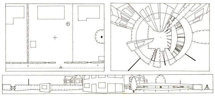
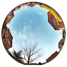 My first thoughts were to use a fish-eye on camera on its back so that the image surface (film plane) was horizontal. Such lenses produce tremendous distortions in the image, but with the film plane horizontal, all the rays from the centre point to features around the rim of the image are true. With the camera at a know location all the angles to the points of interest would be the same as if measured with a theodolite. At that time the plotting of detail measured by theodolite was done by placing a large protractor under the plotting trace at the point representing the Theodolites location and orientating it to another identifiable point. The image from the fish-eye lens could be used in the same way. The intersection of rays from different images taken at different locations would plot the points of interest in exactly the same way as in Plane Table surveying. Using a photographic solution meant that all the detail on the room was capture at one time so that if additional detail needed to be plotted, this could be done without having to revisit the site. However, this idea had one major drawback, all the information was compressing into a narrow band around the perimeter of the image making it very difficult to interpret. Also, getting the exposure right, especially outdoors, can be tricky.
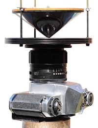 The principle was there and this lead to my invention of the conical mirror or conical prism. This provided a distorted image, but one in which all the points of detail were radial from the centre of the image.
 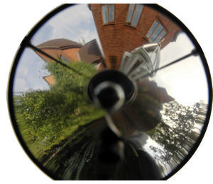 The images produced from such a device could be used in the same way as those from a fish-eye lens, but it is also possible to calibrate the image so that the radial distance from the centre could be used to calculate the vertical angle above and below the horizon to calculate heights. I was granted a Patent for this invention in 1975, but being of very limited funds I let this lapse when the laws were changed in the early 1980s and the annual fees increased dramatically. The patent process was itself challenging as I was then working in remote locations in Malawi on a road project so the only means of communication was by air mail post on the occasions that I visited town. Even more challenging was trying to construct such a device. I proved the concept to my own satisfaction by placing prisms on the filter in front of a camera lens. The angle of acceptance of the device is a function of the angles used in its construction together with the angle of acceptance of the lens being used, which in turn is dependent of the focal length of the lens and the image format. Before a device can be constructed it is therefore necessary to decide on which lens it is to be used with. This is further complicated by the fact that the section rotated through 360° does not have to be made up of straight lines, as shown in the patent drawings. If a conical mirror is to be constructed the line representing the mirrored surface can be straight, convex or concave, and if a prism is to be the end result the all three sides of the triangle can be straight, convex or concave.

In the 19070s the personal computer was science fiction, but with today’s technology the circular images could be digitised and the points calculated on the computer. However, the need for these specialised images has been nullified by the power the computer as the same results can be achieved with ‘conventional’ images if we know their location and orientation in space, but I still feel that being able to capture a full 360° panoramic image in an instant has its advantages.
![]()