
Determination of the No Parallax Point of a Lens Using a Cross Line Laser
Garry George has posted an inspired innovation for using a laser to determine the NPP (No Parallax Point or, on-axis, Entrance Pupil location) of a lens by using a Cross Line Laser. When the laser beam travels along the path of a ray that meets the NPP of a lens the image projected onto a surface (white card) behind the lens is maximised and the ray can then be drawn onto the paper. These rays can be constructed for a variety of angles of incidence and the NPP determined. Using a laser with a line rather than a point simplifies the process as it is no longer necessary to build a mount for the laser and cradle for the lens to ensure the laser line and principal ray of the lens are in the same plane and there is no need to mount the laser on an Alidade to transfer the line of the laser onto the paper making this a simple way of accurately determining the NPP. The process is similar to using a Laser Pointer as all that is required is the lens itself and the laser and is considerably quicker. Today the cost a Cross Line Laser is not much more than an Adjustable Laser Gun Sight or even a Laser Pointer making determining the NPP of a lens using a Cross Line Laser an attractive option.
Laser safety: When using lasers ensure that they are used in a safe manner and always follow the manufacturer’s safety instructions.
Precision
 Using a laser is an accurate method for determining the NPP of a lens as demonstrated in showing the sub-millimetre difference when the Fujinon GF 23mm Lens was mapped with and without an ND filter, but it is arguable that a linear laser provides a more precise result than a spot (dot) laser. When using a Laser Pointer the laser line is transferred to the paper using the Alidade and any misalignment, even a small amount, will influence the result. With a linear laser the line can be directly recorded on the paper as it is visible. Also, the projected image of a Laser Pointer is maximised when the beam passes through the NPP, but the final location is open to interpretation whereas a vertical laser line can be positioned precisely.
Working Surface
A table or board that paper can be taped to and that is large enough to accommodate the lens and the Cross Line Laser should be used, but should not be too large to make working around the lens difficult. Typically less area is required than when using a Laser Pointer and Alidade.
 Mounting the Lens
The lens needs to be supported so that it does not move during the measurement process and enables its position to be transferred to the paper. There is no need to make a cradle as described in Laser Pointer. The lens could be placed on a bean bag as suggested by Garry, or held in place with Plasticine or Sugru (cling film between the lens and material will stop the material sticking to the lens) or even LEGO.
Determination of the NPP
 The application will dictate the accuracy that the NPP needs to be measured to. In the past we have tended to map the NPPs for a pattern of rays to decide which is best for our application. Using a laser line means that the NPP for a particular purpose, such as the number of shots round for a 360° Panorama, can be easily determined without having to map a pattern of rays.
  Typically for a 360° Panorama we require the NPP where the adjacent images join* and this can be quickly measured for the two rays either side of the principal ray using a Cross Line Laser. The accuracy of the result improves as the angle between the join* ray and the principle ray increases so if the angle is acute (e.g. 22.5°) it is useful to also measure the NPP for say 45° as a check as the two locations should be very close.
All that is necessary is to record the location of the front of the lens, the principle ray and the relevant rays for the NPP and the position of the desired NPP is obtained making using the Cross Line Laser an ideal method.
*The angle of the ‘joining ray’ depends on the number of shots round for a 360° Panorama. For example: 45° for four shots round, 30° for six shots round and 22.5° for eight shots round.
Mapping the Lens
If the application requires the pattern of NPPs to be mapped the lens should be carefully recorded using precision measurements with tools such as Digital Vernier Calipers or Electronic Calipers rather than rely on the measurements to locate its position on the paper with a setsquare and probe.
Template
 The laser can be used to record random rays and measure where they intersect the principal ray to determine the NPP, but it is more effective, precise and efficient to plot the rays at regular intervals such as every 15°, 10° or even 5°. The template should also include Control Points so that it can be orientated and scaled correctly when scanned to determine the NPP digitally using a CAD application.
Positioning the Lens
The proceeds is more effective, precise and efficient if the lens is positioned as close to the correct location for the NPP as possible so it is worth using the laser to align the axis of the lens and then move the lens along this line with the laser at 45° each side of the axis, which is easily and quickly achieved using a Cross Line Laser.
Lens Location
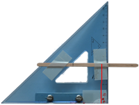
 It is imperative that the position of the lens is recorded relative to the lines plotted using the laser. The position of the lens can be mapped using a ‘probe’ which can be constructed using a setsquare. This should be used to position the ‘mapped lens’ rather than to ‘map’ the lens as there are likely to be small (sub millimetre) errors in this process. Make a note of the points plotted using this process.
Recording the Direction of the Rays
 Line up the laser line with a line on the Template then move the Cross Line Laser parallel to this line until the vertical laser line is observed on the surface (white card) behind the lens. This process is repeated for each angle line on the Template.
 The number of rays that can be recorded will depend on the angle of view of the lens.
Care must be taken when moving the Cross Line Laser back and forth as it is possible to introduce a slight skew which will introduce error into the measurement but the fact that the laser line is visible on the paper makes this process easier than when using a Laser Pointer.
The intersection of the rays to the principal ray is stronger the greater the ‘angle of cut’. A slight skew will introduce a larger error for the rays with a narrow angle to the principal ray (e.g. 10°) than rays cutting the principal ray at a greater angle (e.g. 60°).
Graphical Interpolation
Once the positions of the lens and the rays passing through the NPP have been plotted the NNP can be interpolated by projecting the lines plotted at the various angles to where they intersect the principal ray (lens axis).
This solution is sufficient for some application but a more rigorous solution can be achieved by scanning the plots and using a CAD application to determine the NPP.
Digital Interpolation
Interpolating the position of the NPP using a CAD application will provide a more precise solution than the graphic interpolation. There are a variety of CAD applications suitable for digitally interpolating the NPP. Being able to view the data at a scale larger than 1:1 on a computer, as in the graphical case, increases the precision of the result.
Some lenses have more movement of the NPP along the principal ray than others. For example the Nikon 10.5mm Fisheye has some 6mm difference between the NPP at 10° either side of the principal ray and at 70° either side of the principal ray.
In such cases the measurement can be further enhanced by creating a new Template with the rays passing through the relevant NPPs instead of a single point as there should be little or no deviation from the drawn lines to get the maximum laser spot for each line.
Laser safety: When using lasers ensure that they are used in a safe manner and always follow the manufacturer’s safety instructions.
January 2025
![]()
Procedure
- Create the Template
Either draw the lines graphically on the paper or use a CAD Application and print it
The template should consist of a centre line, two lines at 45° from the centre line and the lines of interest. e.g. 22.5° for eight shots round or lines at regular angular intervals to ‘map’ various locations for the NPP
The template should also have ‘control points’ for orientation and scaling if a CAD Application is to be used to determine the NPP - Place the Template
Choose a suitable surface to place the template
It is recommended the template is fixed to the surface (e.g. with masking tape) to prevent movement during the measurement process - Place the Lens
Place the lense using a suitable mount so that the Principal Ray is aligned with the centre line on the template and the estimated position of the NPP is at the point at which the lines on the template converge - Align the Lense
 Align the laser with the centre line on the template and fine tune the position of the Lens so that the image of the Laser projected by the Lens is maximised
 - Note: The horizontal plane of the Cross Line Laser should be separated from the plane through the principal ray of the lens by 5mm or more. The planes should not be coincident as the horizontal laser will obscure the image of the laser passing through the lens for rays at the wider angles of incidence.
- Adjust the location of the Lens
Align the Laser with one of the lines at 45° to the centre line and and move the lens along the centre line so that the image of the laser projected by the lens is maximised
Align the Laser with the other line at 45° to the centre line and and check that the image of the laser projected by the lens is maximised
The NPP of the Lens is now close to the intersection of the lines on the template - Plotting the Principal Ray (centre line) of the Lens
Align the laser with the centre line on the template so that the image of the laser projected by the lens is maximised and mark the location of the Laser on the paper with two marks
The marks should be as far apart a possible. i.e. one near the front of the Lens and one near the Laser - Plotting the Rays Intersecting the Principal Ray
Align the Laser with each line on the template in turn, including the lines at 45° to the centre line, and mark the line of the Laser on the paper
The marks should be as far apart a possible. i.e. one near the front of the Lens and one near the Laser - Plotting the Position of the Lens
The front of the Lens should be recorded on the paper using a set-square or other right angled device
Care must be taken not to move the Lens when bringing the set-square into contact with the Lens
It is recommended that several points are recorded to minimise any small errors in transferring the position of the Lens to the paper - Determining the NPP
The NPP can now be determined either graphically or using a CAD Application
Graphically by drawing a line through the the two marked points for each line until it intersects the Principal Ray line (centre line) on the paper locating the NPP or
Scanning the template and digitising the marked points and control points in a CAD Application and constructing the intersection of the lines with the Principal Ray
Using a CAD Application the determine the NPP will provide a more accurate solution - Result
The relationship of the NPP to the front of the Lens is now determined
Laser safety: When using lasers ensure that they are used in a safe manner and always follow the manufacturer’s safety instructions.
January 2025
![]()
 Samyang 14mm f2.8 Nikon Z Fit